
Bridgeless power factor correction circuit

A power factor correction and circuit technology, applied in circuit devices, emergency protection circuit devices, output power conversion devices, etc., can solve problems such as EMI characteristics that cannot improve work efficiency, and achieve improved EMI characteristics, reduce costs, and improve power density. Effect

Inactive Publication Date: 2012-10-24
EMERSON NETWORK POWER ENERGY SYST NORTH AMERICA
View PDF5 Cites 18 Cited by
  • Summary
  • Abstract
  • Description
  • Claims
  • Application Information

AI Technical Summary

Problems solved by technology

[0015] To sum up, the existing bridgeless PFC circuit can not improve the work efficiency and improve the EMI characteristics at the same time

Method used


Image

  • Bridgeless power factor correction circuit
  • Bridgeless power factor correction circuit
  • Bridgeless power factor correction circuit

Examples


Embodiment Construction

[0059] In order to enable those skilled in the art to better understand and implement the technical solution of the present invention, a bridgeless PFC circuit in the prior art will be firstly introduced below.

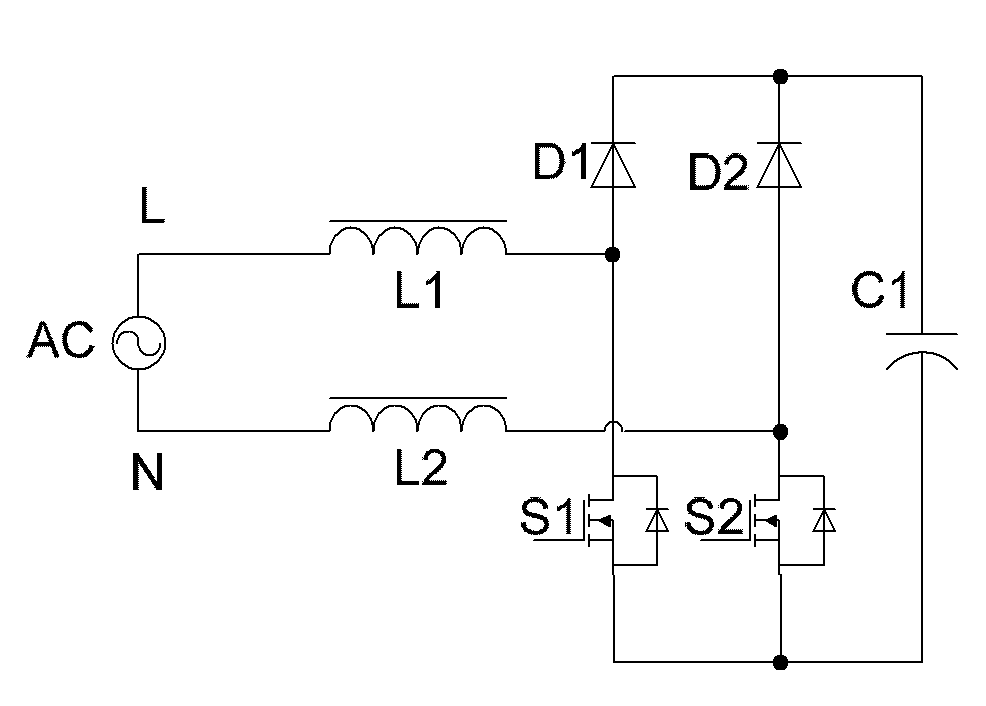
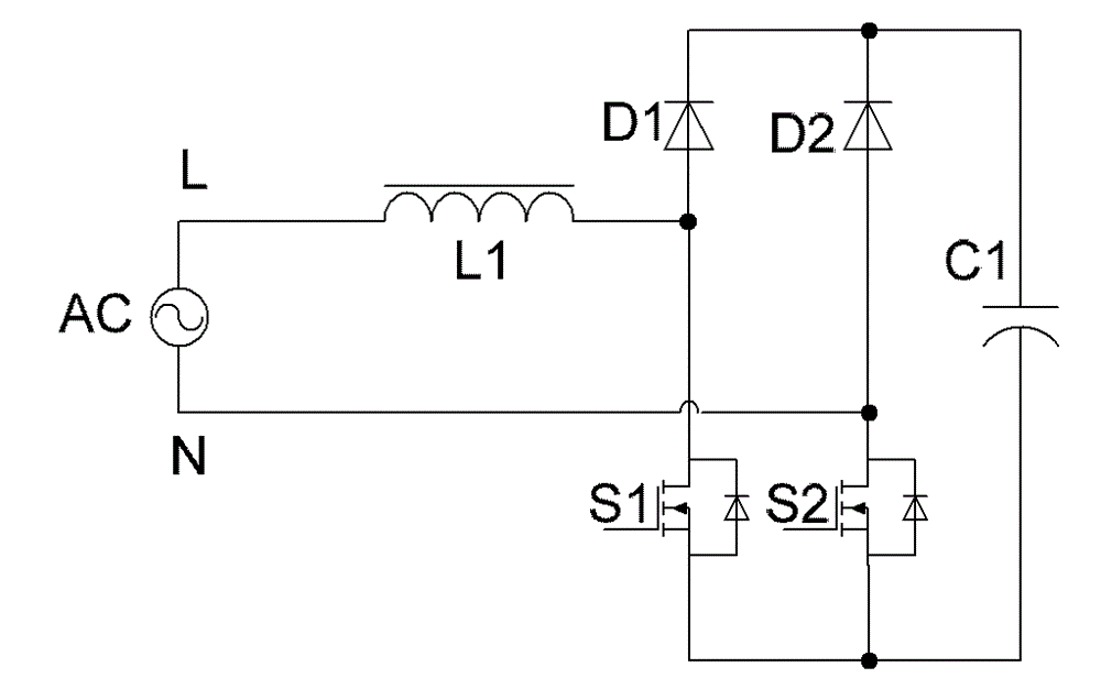
[0060] see Figure 5 , which is a schematic diagram of a bridgeless PFC circuit provided by the prior art.

[0061] The bridgeless PFC circuit includes a high-frequency bridge arm and a low-frequency bridge arm, wherein the high-frequency bridge arm includes a first switch tube S1 and a second switch tube S2 connected in series, and the low-frequency bridge arm includes a series-connected first diode D1 and a second switch tube S2. the second diode D2.

[0062] Both ends of the low-frequency bridge arm and the high-frequency bridge arm are connected in parallel to both ends of the capacitor C1.

[0063] The common end of the first diode D1 and the second diode D2 is connected to one end of the AC power source AC, and the common end of the first switch tube S1 and th...


PUM


Abstract

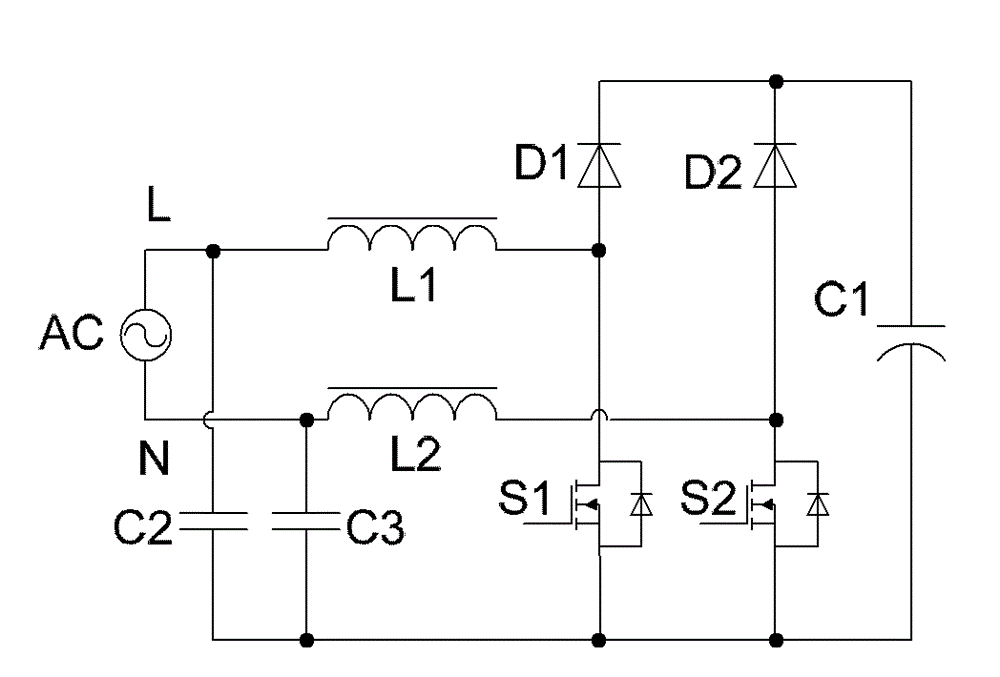
The invention provides a bridgeless power factor correction circuit. A low-frequency bridge arm comprises two diodes connected in series, including a first diode and a second diode; a three-port network comprises a switch tube and an inductor; and the low-frequency bridge arm and the three-port network work jointly to realize power factor correction; a lightning and surge protection bridge arm comprises two diodes connected in series, including a third diode and a fourth diode; a capacitor is connected between the two ends of the low-frequency bridge arm; a second capacitor is connected between the two ends of the lightning and surge protection bridge arm; the common end of the first diode and the second diode is connected with one end of an alternating current source; the common end of the third diode and the fourth diode is connected with the other end of the alternating current source; a third capacitor is connected between the first end and the second end of the three-port network; and the third end of the three-port network is connected with the common end of the third diode and the fourth diode. Lightning and surge protection is achieved through the lightning and surge protection bridge arm composed of the two diodes connected in series, so the EMI (Electro-Magnetic Interference)feature of the circuit is improved; the cost of the whole circuit is reduced; and the working efficiency is improved.

Description

technical field [0001] The invention relates to the technical field of power factor correction, in particular to a bridgeless power factor correction circuit. Background technique [0002] Power factor refers to the relationship between effective power and total power consumption (apparent power), that is, the ratio of effective power divided by total power consumption (apparent power). The power factor can measure the degree to which electricity is effectively used. When the power factor is larger, it means that the power utilization rate is higher. [0003] The function of the power factor correction (PFC, Power Factor Correction) circuit is to improve the power factor. [0004] Several bridgeless power factor correction circuits in the prior art are introduced below. Bridgeless here means that there is no rectifier bridge. [0005] see figure 1 , which is a schematic diagram of a dual Boost bridgeless PFC circuit in the prior art. [0006] The working process of this...

Claims


Application Information

Patent Timeline
Patent Type & Authority Applications(China)
IPC IPC(8): H02M1/42H02M1/44H02H9/04H02H9/02
CPCY02B70/126H02M1/44H02M1/4225H02M1/4233H02M7/062Y02B70/10Y02P80/10H02M1/0085
Inventor 王琳化许峰武志贤李祥生
Owner EMERSON NETWORK POWER ENERGY SYST NORTH AMERICA
Learn More