Vasculature device

A technology of vascular system and guide wire, applied in the direction of catheter, trocar, medical science, etc., can solve problems such as looseness and reduced ability to pull out clots

Inactive Publication Date: 2012-10-24
GORE ENTERPRISE HLDG INC
View PDF16 Cites 5 Cited by
  • Summary
  • Abstract
  • Description
  • Claims
  • Application Information

AI Technical Summary

Problems solved by technology

This leads to a trade-off between making the "corkscrew" floppy (which reduces its ability to withdraw clots), or customizing a stiffer microcatheter (limiting access to the procedure)

Method used


Image

  • Vasculature device
  • Vasculature device
  • Vasculature device

Examples


example

[0048] Without intending to limit the scope of the invention, the following examples illustrate how to make and / or use various embodiments of the invention.

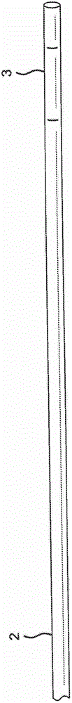
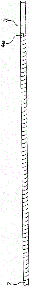
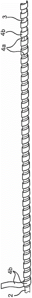
[0049] A vasculature device similar to Figures 3a, 3b and 3c was fabricated using the following components and assembly process.

[0050] The following parts are used.

[0051] A 0.005" (0.127 mm) diameter nitinol wire (Fort Wayne Metals, Fort Wayne, IN) with a distal end heat-cured to a straight coil (not tapered) makes A s about 33°C, A f About 42°C. The wire is shape-cured using shape-curing heat treatment techniques known in the art.

[0052] Stainless steel laser cut helical secondary tubing (Creganna, Marlborough, MA) with an ID and OD of 0.0093″x0.0132″ (0.236x0.335mm), respectively. Specifies the pitch of the helical cut. A 2 mm portion near the distal end of the paratube is left uncut to provide a suitable location for crimping.

[0053] 0.005″ (0.127mm) stainless steel machining mandrel.

[0054] Lengths...


PUM


Abstract

A vasculature device with a wire with a shaped set portion, an electrically conductive path, an electrical connector connecting the wire to the electrically conductive path at a point distal to the shaped set portion, and a hypotube encasing the wire, electrically conductive path and electrical connector is provided. The vasculature device can be actuated from a low-profile configuration to a deployed configuration by heating of the wire, and in particular the shaped set portion of the wire, via application of an electrical current to the wire. The vasculature device is useful in removal of clots, thromboemboli and foreign bodies from the vasculature, and in particular the cerebral vasculature, and as steering wires or guidewires.

Description

[0001] Cross-references to related applications [0002] This application claims priority to US Provisional Patent Application No. 61 / 265,501, filed December 1, 2009, which is hereby incorporated by reference in its entirety. technical field [0003] The present invention relates to vasculature devices, for example for removing objects such as thrombus or other foreign matter from the vasculature of a patient. In particular, the present invention relates to devices for removing thrombus from the cerebral vasculature of a patient. The devices of the present invention may also be used as steerable guide wires or steering wires within a patient's vasculature. Background technique [0004] The use of mechanical devices to restore patency to blocked vessels is known. These devices fall into a number of categories, ranging from hydraulic thrombus removal, to rotary cutting blades for calcified atheromas, to inflatable devices to comminute or pull thrombi, or to be either self-e...

Claims


Application Information

Patent Timeline
Patent Type & Authority Applications(China)
IPC IPC(8): A61B17/221A61B17/00A61B17/22
CPCA61B2017/22038A61B17/320725A61B17/221A61B2017/2217A61B2017/00867A61B2017/22042A61B17/22A61B18/08A61M25/01A61B17/34
Inventor D·C·小埃弗森D·C·凯切B·M·特拉普N·R·威廉姆斯
Owner GORE ENTERPRISE HLDG INC
Why Eureka
Try Eureka