
Pneumatic control loop for dispensing

A pneumatic control and dispensing technology, which is applied to devices and coatings that apply liquid to the surface. It can solve the problems of easy dispensing of dispensing needles and uneven dispensing volume, so as to protect the environment and improve dispensing accuracy. , the effect of convenient control

Inactive Publication Date: 2012-10-31
TONGLING FUSHI SANJIA MACHINE
View PDF4 Cites 12 Cited by
  • Summary
  • Abstract
  • Description
  • Claims
  • Application Information

AI Technical Summary

Problems solved by technology

[0003] The purpose of the present invention is to solve the problem of uneven dispensing amount and easy dripping of dispensing needles when not dispensing during the LED packaging process

Method used


Image

  • Pneumatic control loop for dispensing

Examples


Embodiment Construction

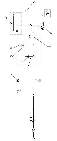
[0008] The present invention is a pneumatic control circuit for dispensing, such as figure 1 As shown, it includes a main pipe 10 connected with a dispensing needle to supply air to the dispensing needle, an electric proportional valve 1 is connected in series on the main pipe 10, and a bypass pipe 9 is provided on the front end of the electric proportional valve 1 , the bypass pipeline 9 is connected with the control interface pipe of the electric proportional valve 1, the pressure switch 7 and the power amplifier 5 are connected in series in the bypass pipeline 9, the power amplifier 5 is connected with the control circuit 6, the bypass pipeline 9, The positive pressure switch 7, the control circuit 6, the power amplifier 5 and the electric proportional valve 1 together constitute a voltage stabilizing device. The main pipeline 10 is connected in parallel with a negative pressure pipeline 11, and the end of the negative pressure pipeline 11 is connected with the outlet ...


PUM


Abstract

The invention discloses a pneumatic control loop for dispensing. The pneumatic control loop comprises a main pipeline, a voltage stabilizing device is connected onto the main pipeline in series, a negative pressure pipeline is connected onto the main pipeline in parallel, the tail end of the negative pressure pipeline and an outlet of an electric proportional valve are jointly connected onto two input ports of a change valve, an outlet of the change valve is connected with an inlet of a dispensing needle tube, and a flow control valve, a vacuum device and a negative pressure switch are sequentially connected onto the negative pressure pipeline in series. The pneumatic control loop achieves digital control and digital display of pressure control and brings convenience to control of dispensing amount. The electric proportional valve is arranged in the loop so that a pressure value of a pressure loop is stabilized in a certain scope and dispensing accuracy is improved. The negative pressure pipeline is arranged to provide negative pressure for the dispensing needle tube when the dispensing needle tube does not dispense, so that glue liquid in the dispensing needle tube can not drop under action of gravity, raw materials are saved, and environment are protected.

Description

technical field [0001] The invention relates to a control circuit for encapsulation dispensing in electronic manufacturing industry. Background technique [0002] Glue dispensing is a process, also known as sizing, gluing, glue pouring, glue dropping, etc. It is to smear, fill, and drop electronic glue, oil or other liquids on the product, so that the product can stick and fill. Sealing, insulation, fixing, smooth surface and so on. LEDs have developed rapidly in recent years due to energy saving. During the production process of LEDs, glue needs to be dispensed to fix and package the chips. At present, the time-pressure fluid dispensing method has become the most commonly used dispensing method in the electronics manufacturing industry due to its low cost, easy operation, easy maintenance and wide application. It supplies air to the main line through the solenoid valve and controls dispensing to the dispensing needle. Typical time-pressure dispensing system is in the dis...

Claims


Application Information

Patent Timeline
Patent Type & Authority Applications(China)
IPC IPC(8): B05C11/10B05C5/02
Inventor 班有根陈昌太童中志杨鑫高双全
Owner TONGLING FUSHI SANJIA MACHINE
Learn More