Efficient high-pressure liquid air energy storage/release system

A technology of liquid air and high-pressure air, which is applied in the direction of gas turbine devices, machines/engines, mechanical equipment, etc., can solve the problems of high energy, consumption, and reduce the operating efficiency of energy storage systems, and achieve high energy density and high efficiency.

Active Publication Date: 2012-10-31
INST OF ENGINEERING THERMOPHYSICS - CHINESE ACAD OF SCI
View PDF4 Cites 45 Cited by
  • Summary
  • Abstract
  • Description
  • Claims
  • Application Information

AI Technical Summary

Problems solved by technology

However, it is necessary to consume relatively high energy in the depressurization and throttling link of the energy storage process and

Method used


Image

  • Efficient high-pressure liquid air energy storage/release system
  • Efficient high-pressure liquid air energy storage/release system
  • Efficient high-pressure liquid air energy storage/release system

Examples


Embodiment 1

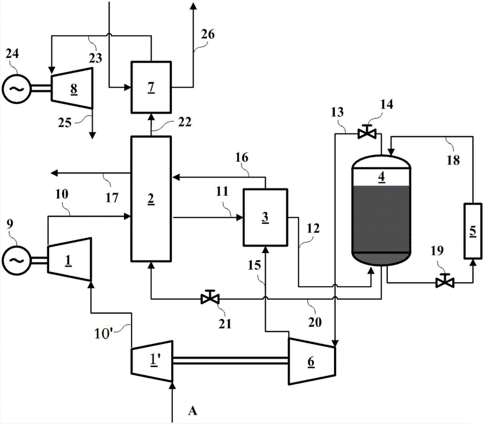
[0041] Such as figure 1 Shown is Embodiment 1 of the high-efficiency high-pressure liquid air energy storage / energy release system of the present invention. Among them, low-pressure compressor unit 1′, high-pressure compressor unit 1, cold accumulator 2, low-temperature heat exchanger 3, high-pressure liquid air storage tank 4, self-supercharger 5, low-temperature expansion unit 6, heat storage / heat exchanger 7, main Expansion unit 8, generator 24, driving motor 9, valves 14, 19, 21, pipelines 10', 10, 11, 12, 13, 15, 16, 17, 18, 20, 22, 23, 25, 26, inlet air A.

[0042] The low-temperature expansion unit 6 is fixedly connected to the common transmission shaft of the low-pressure compressor unit 1 ′, the driving motor 9 is fixed to the common transmission shaft of the high-pressure compressor unit 1 , and the common transmission shaft of the generator 24 and the main expansion unit 8 is fixedly connected. The inlet of the low-pressure compressor unit 1' is connected to air A...

Embodiment 2

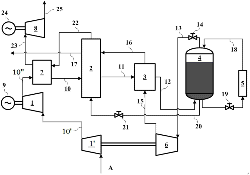
[0047] figure 2 It is Embodiment 2 of the high-efficiency high-pressure liquid air energy storage / energy release system for storing and releasing compression heat of the present invention. Its main structure is the same as that of Embodiment 1. The high-temperature and high-pressure air generated by the high-pressure compressor unit 1 passes through the heat storage / heat exchanger 7' enters the cold accumulator 2 after cooling down, and the heat accumulator / heat exchanger 7 mainly stores and releases the compression heat of the compressed air.

[0048] When storing energy, the high-pressure air at the outlet of the high-pressure compressor unit 1 first enters the heat storage / heat exchanger 7, and the heat generated by the compressed air is absorbed by the heat storage material, while the temperature of the high-pressure air drops to normal temperature. The normal-temperature high-pressure air exiting the heat storage / heat exchanger 7 enters the cold storage 2 sequentially, a...

Embodiment 3

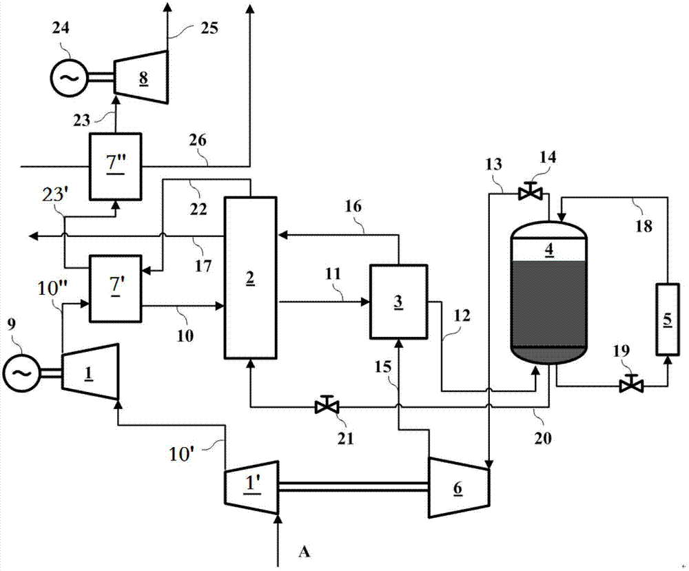
[0050] image 3 It is the embodiment 3 of the combination of the high-pressure liquid air energy storage system of the present invention and solar thermal power generation or industrial waste heat utilization. Its main structure is the same as that of embodiment 2, and the connecting part with the solar collector or industrial waste heat pipeline is added. The high-temperature fluid from the solar heat collector or industrial waste heat enters the high-temperature heat storage / heat exchanger 7″ through the pipeline 26, and the high-temperature fluid releases heat and cools down in the high-temperature heat storage / heat exchanger 7″. The main high-pressure air exiting the heat storage / heat exchanger 7' is heated to a high temperature in the high-temperature heat storage / heat exchanger 7", and then enters the main expansion unit 8 through the pipeline 23 to expand and perform work.


PUM


Abstract

The invention discloses an efficient high-pressure liquid air energy storage/release system, which comprises an energy storage subsystem and an energy release subsystem; in the energy storage subsystem, a low-pressure compressor set (1'), a high-pressure compressor set (1), a cold accumulator (2), a low-temperature heat exchanger (3), a high-pressure low-temperature storage tank (4), a low-temperature expansion machine set (6) and a low-temperature heat exchanger (3) are communicated in sequence; a driving unit (9) drives the high-pressure compressor set (1), and the low-temperature expansion machine set (6) drives the low-pressure compressor set (1'); the energy release subsystem comprises a self-pressurization unit (5) and an acting unit; and the high-pressure and low-temperature storage tank (4), the cold accumulator (2), a heat accumulator/heat exchanger (7) and a main expansion machine set (8) are connected in sequence, and the main expansion machine set (8) drives a power generator (24). The energy storage system disclosed by the invention has the advantages of high energy density, high efficiency, no power consumption in the power generation stage, suitability for various power stations, no greenhouse gas generation, capability of recovering intermediate-temperature and low-temperature waste heat and the like.

Description

technical field [0001] The invention relates to the technical field of energy storage, and is a high-efficiency energy storage / release system based on high-pressure liquid air to store energy and utilize the stored energy to generate electric energy. Background technique [0002] With the increasing popularity of renewable energy (wind energy, solar energy, etc.), and the urgent need for grid peak regulation, improving grid reliability, and improving power quality, the importance of power energy storage systems has become increasingly prominent. Large-scale power energy storage technology can effectively solve the contradiction between peak and valley differences in power production and use; it can provide the reliability of power system power supply; it can solve the key technology of intermittent energy generation instability such as wind power, solar energy, and tidal energy. [0003] At the same time, the electric energy storage system is also a key technology of the dis...

Claims


Application Information

Patent Timeline
IPC IPC(8): F02C6/16
CPCY02E60/15Y02E60/16
Inventor 王亮陈海生刘金超盛勇张新敬谭春青
Owner INST OF ENGINEERING THERMOPHYSICS - CHINESE ACAD OF SCI
Why Eureka
Try Eureka