Pipe wall bonding and molding method of air-inflation stretching arm

A molding method and technology of extending arms, which are applied in the direction of connecting components, mechanical equipment, etc., can solve the problem that the workbench cannot bond the arc-shaped reinforcing strip and the flat-shaped velcro at the same time. The effect of cleanliness

Inactive Publication Date: 2012-10-31
HARBIN INST OF TECH
View PDF5 Cites 6 Cited by
  • Summary
  • Abstract
  • Description
  • Claims
  • Application Information

AI Technical Summary

Problems solved by technology

[0003] The purpose of the present invention is to solve the existing problem that the arc-shaped reinforcing strip and the flat buckle cannot be bonded at the same time on the ordinary flat workbench, and to provide a tube wall bonding and forming method of the inflatable extension arm

Method used


Image

  • Pipe wall bonding and molding method of air-inflation stretching arm
  • Pipe wall bonding and molding method of air-inflation stretching arm

Examples


specific Embodiment approach 1

[0025] Specific Embodiment 1: The pipe wall bonding molding method of an inflatable stretch arm in this embodiment is carried out according to the following steps:

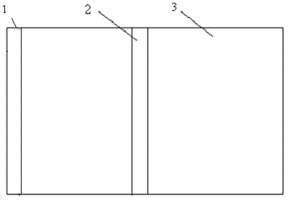
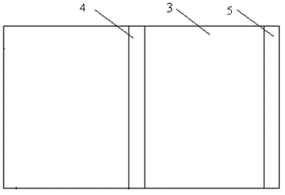
[0026] 1. On the front of the laminated aluminum film, a buckle bonding area and a tube bonding area A are set, wherein the tube bonding area A is at the edge of one end of the laminated aluminum film; A reinforcing strip bonding area is provided at a position corresponding to the buckle bonding area, and a tube-forming bonding area B of the same length and width is set at a position opposite to the edge where the tube-forming bonding area A is located;

[0027] Two, the surface of the laminated aluminum film is pasted with paper tape in areas other than the buckle bonding area, the tube bonding area A, the reinforcement strip bonding area and the tube bonding area B;

[0028] 3. Grind the buckle bonding area, tube bonding area A, reinforcement bar bonding area and tube bonding area B with sandpaper of P2000 along...

specific Embodiment approach 2

[0040] Embodiment 2: This embodiment differs from Embodiment 1 in that: the thickness of the adhesive applied in Step 4 and Step 5 is 0.1-0.5 mm. Others are the same as in the first embodiment.

specific Embodiment approach 3

[0041] Embodiment 3: The difference between this embodiment and Embodiment 1 or 2 is: the room temperature curing 3d described in Step 4 and Step 5. Others are the same as in the first or second embodiment.

[0042] Verify effect of the present invention by following test:

[0043] The pipe wall bonding molding method of a kind of inflatable extension arm of this test is carried out according to the following steps:

[0044]One, on the front of the laminated aluminum film 3, the buckle bonding area 2 and the tube bonding area A1 are set, wherein the tube bonding area A1 is at the edge of the laminated aluminum film 3 one end; On the back side of the film 3, a reinforcing strip bonding region 4 is arranged at a position corresponding to the buckle bonding region 2, and a tube-forming bonding region of the same length and width is arranged at an opposite side position of the edge of the tube-forming bonding region A1. Zone B 5;

[0045] Two, the surface of the laminated alumi...


PUM


Abstract

The invention discloses a pipe wall bonding and molding method of an air-inflation stretching arm, relating to the pipe wall bonding and molding method and aiming to solve the problem that the traditional common planar worktable can not be used for bonding arc-shaped reinforcing strips and planar hook and loop fasteners at the same time. The pipe wall bonding and molding method comprises the steps of: 1, grinding a laminated aluminum thin-film hasp bonding area, a pipe-molding bonding area A, a reinforcing strip bonding area and a pipe-molding bonding area B, and cleaning with acetone; 2, coating an adhesive, standing at room temperature for 30 min, bonding nylon hasps firstly and then bonding the reinforcing strips; and (3) increasing pressure in a cylindrical thin-film air bag to 20kPa, coating a laminated aluminum thin film on the air bag, winding bandages uniformly, increasing the pressure to 50kPa, standing at room temperature for 96h, reducing the pressure, removing bandages to complete the bonding and molding of the pipe wall. According to the invention, the average peel strength between the hook and loop fastener and the pipe wall of the air-inflation stretching arm is 0.25KN / m and is in increased by two times compared with that of the traditional bonding process. The pipe wall bonding and molding method is applied to the field of pipe walls of the air-inflation stretching arms.

Description

technical field [0001] The invention relates to a pipe wall bonding forming method. Background technique [0002] The tube wall of the existing inflatable extension arm has elastic reinforcement strips inside to improve the stiffness of the extension arm, and there are Velcro fasteners on the outside to control the expansion. The reinforcement strips are made of fiber composite materials, and their thickness is generally 0.3mm. Its cross-section is arc-shaped with the same curvature as the tube wall curvature of the formed extension arm. When the pipe wall is made of laminated aluminum film with a thickness of about 0.1mm, the general method is to first bond the reinforcing strip to the inner surface of the stretch arm, and then place it on a soft board and press it with a sandbag at room temperature for 96 hours; The outer surface of the arm is bonded with 4 reinforcement strips, and then placed on the soft board and pressed with sandbags at room temperature for 96 hours t...

Claims


Application Information

Patent Timeline
Patent Type & Authority Applications(China)
IPC IPC(8): F16B11/00
Inventor 谭惠丰卫剑征高树义于尧炳杨霞王伟志张胜李兵汪逸然赵秀兰
Owner HARBIN INST OF TECH
Why Eureka
Try Eureka