
Method for measuring DC (Direct Current) resistances of transformer windings

A technology of transformer winding and DC resistance, applied in the direction of measuring resistance/reactance/impedance, measuring electrical variables, measuring devices, etc., can solve the problems of unstable measurement data, great influence of measurement, and slow stability of test current, etc.

Inactive Publication Date: 2012-10-31
CHINA THREE GORGES CORPORATION
View PDF3 Cites 17 Cited by
  • Summary
  • Abstract
  • Description
  • Claims
  • Application Information

AI Technical Summary

Problems solved by technology

When measuring the DC resistance of the low-voltage winding by the magnetic-assisted method, the excitation state of the iron core is almost saturated. When the charging current is cut off, there is still a large residual magnetism in the iron core, which will have a great impact on subsequent measurements.
Therefore, in the process of measuring the DC resistance of the winding, the adverse effects of residual magnetism should be avoided. Even if the residual magnetism in the three-phase three-iron core column is eliminated as much as possible during the measurement, the reverse magnetization will be avoided, which will cause the test current to stabilize slowly and the measurement data will not be accurate. Stablize

Method used


Image

  • Method for measuring DC (Direct Current) resistances of transformer windings
  • Method for measuring DC (Direct Current) resistances of transformer windings
  • Method for measuring DC (Direct Current) resistances of transformer windings

Examples


Embodiment Construction

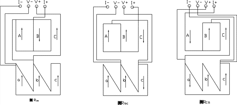
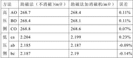
[0015] A method for measuring the DC resistance of a transformer winding. When measuring the DC resistance of a large transformer winding on site, a DC resistance tester and a demagnetizer are used together.

[0016] Step 1: Use a degausser to eliminate the residual magnetism in the transformer core. The degaussing machine is connected to a 220V power supply and must be well grounded. Connect the test wires of phase A and B of the transformer to the "degaussing output" terminal of the degaussing machine. Start the degaussing machine, the degaussing starts, and the progress is displayed on the screen. After the degaussing of the AB phase is completed, change the line to the BC phase, and repeat the above operations until all the residual magnetism in the transformer core is eliminated. This step mainly eliminates the residual magnetism in the iron core when the transformer is removed, and provides conditions for DC resistance measurement.

[0017] Step 2: Use the DC resistanc...


PUM


Abstract

A method for measuring DC resistances of transformer windings comprises the following steps of: 1, connecting an AB-phase test wire of a transformer to a degaussing machine, starting the degaussing machine, changing the wire to a BC phase after the AB phase is degaussed, and repeating the above steps till all residual magnetisms in an iron core of the transformer is eliminated; measuring the DC resistance Rac of a low-voltage side winding ac and the DC resistance RAO of a high-voltage side winding AO by using a magnetism optimization method through a DC resistance testing instrument, and repeating the step 1 to eliminate the residual magnetisms in the iron core of the transformer; measuring the DC resistance Rab of a low-voltage winding ab and the DC resistance RBO of a high-voltage side winding BO by using the magnetism optimization method through the DC resistance testing instrument, and repeating the step 1 to eliminate the residual magnetisms in the iron core of the transformer; and measuring the DC resistance Rca of a low-voltage winding ca and the DC resistance RCO of a high-voltage side winding CO by using the magnetism optimization method through the DC resistance testing instrument, and repeating the step 1 to eliminate the residual magnetisms in the iron core of the transformer. According to the method for measuring the DC resistances of the transformer windings, excessive magnetizing inrush current of the transformer no-load closing is avoided and the safety operation of the transformer is protected.

Description

technical field [0001] The invention relates to a method for measuring the DC resistance of a transformer winding, which relates to the field of electrical testing of power equipment. Background technique [0002] According to the requirements of the regulations, the pre-test items of the transformer must include "measurement of the DC resistance of the winding and the bushing", the purpose of which is to: check the welding quality of the winding joints and whether there is a short circuit between the turns of the winding; whether the various positions of the voltage tap changer are in good contact And whether the actual position of the tap changer is consistent with the indicated position; whether the lead wire is broken; whether the winding with multiple wires wound in parallel has broken strands, etc. In the DC resistance test, the longer the test time, the greater the test current, and the greater the residual magnetism. According to DL596-1996 "Electrical Equipment Pre...

Claims


Application Information

Patent Timeline
IPC IPC(8): G01R27/02
Inventor 赵鲲董晓英杜森付海涛张松涛
Owner CHINA THREE GORGES CORPORATION
Learn More