
Automatic pressure balancing device for pressure filter

An automatic balance and pressure device technology, applied in brewing, sludge treatment industrial equipment manufacturing, and papermaking fields, can solve problems such as complex hydraulic systems, scrapped filter presses, increased system failure rates, etc., to achieve stable and reliable system operation and sensitive linkage Performance improvement and protection of safe operation

Active Publication Date: 2016-08-17
王军
View PDF12 Cites 9 Cited by
  • Summary
  • Abstract
  • Description
  • Claims
  • Application Information

AI Technical Summary

Problems solved by technology

[0006] No matter how high the pressure is, the deformation of the tie rod or the deformation and leakage of the mold frame will easily occur. Under such a pressure value, the moisture content in the dehydrated filter cake is still very high, and the dehydrated filter plate still needs to be baked. It can be directly used as other raw materials after being processed in other processes, which is extremely inconvenient and expensive for subsequent transportation and processing.
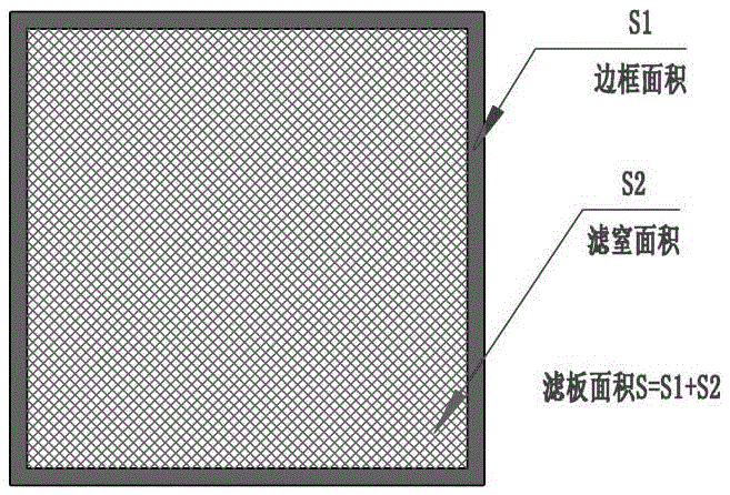
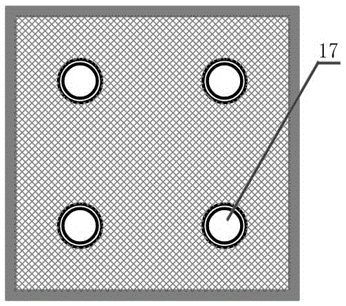
[0007] People increase the filter plate area in order to improve the filter press capacity, but the larger the filter plate area, the greater the pressure on the frame before feeding, which is easy to cause damage to the filter plate. In order to solve this problem, the traditional filter press machine is Multiple support platforms are added in the middle of the filter plate, such as figure 2 , 3 , these support tables can reduce the stress on the frame, but it will bring a series of problems: 1. Reduce the filter area and affect the production capacity
2. The biggest problem is that if some filter cake sticks to these support platforms, the filter cloth will be damaged when the mold is closed next time.
[0009] The pressure conversion cylinder used in the above-mentioned patent uses the area ratio of the rodless chamber and the rod chamber to increase or reduce pressure. It is theoretically feasible, but it is not practical in practice. The reason is that the water is directly connected to the rodless chamber of the pressure conversion cylinder. When working, it is easy to cause a small amount of water or material to enter the rod cavity through the interval around the piston, contaminating the hydraulic oil of the master cylinder. Such consequences, if light, cannot achieve proportional pressure increase or decompression, and if serious, the entire master cylinder may even Filter press scrapped
The above-mentioned patents cannot provide a fixed blank-holding force, and an additional pressure cylinder is required to complicate the hydraulic system, increase the cost, and increase the system failure rate

Method used


Image

  • Automatic pressure balancing device for pressure filter
  • Automatic pressure balancing device for pressure filter
  • Automatic pressure balancing device for pressure filter

Examples


Embodiment Construction

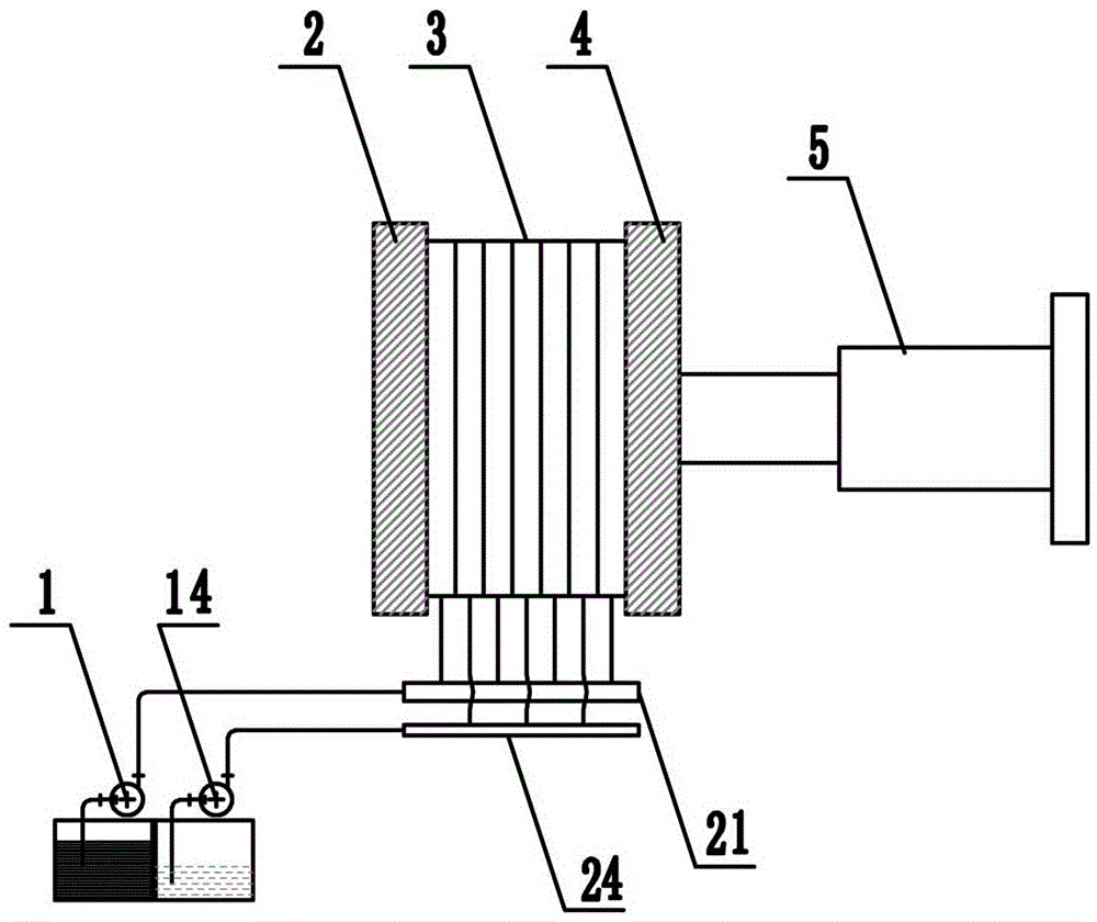
[0049] Figure 4 It is an automatic pressure balance device for a filter press, including thrust plates arranged in sequence, and the optimal number is 80-90 filter plates ( Figure 4 For the schematic diagram, there are only 7 filter plates) and compression plates, the compression plates are connected to the main cylinder, and there are also feed pumps and squeeze water pumps. The feed pumps are connected to an odd number of filter plates through feed pipes, and the squeeze water pumps are connected to dual Several filter plates, the number of filter plates starts from No. 1 close to the compression plate to the direction of the thrust plate, and there are also oil-oil conversion bladders, water-oil conversion bladders, oil-air cylinder combinations, and pressure-stabilizing air storage tanks.

[0050] The feed-oil conversion bladder and the water-oil conversion bladder are respectively connected to the feed pipe and the water inlet pipe.

[0051] The upper part of the oil-a...


PUM


Abstract

The invention relates to the field of equipment manufacturing in the sludge treatment industry and provides an automatic pressure balancing device for a pressure filter. The automatic pressure balancing device comprises a thrust plate, filter plates and a pressing plate, wherein the thrust pate, the filter plates and the pressing plate are arranged in sequence. The pressing plate is connected with a main cylinder. A feeding pump and a water inlet pipe are connected with the filter plates. The automatic pressure balancing device is further provided with a material-oil conversion leather bag, a water-oil conversion leather bag, an oil cylinder and air cylinder assembly and a pressure stabilizing gas storage tank. A small oil cylinder is located on the upper portion of the oil cylinder and gas cylinder assembly, and a large oil cylinder is located on the lower portion of the oil cylinder and gas cylinder assembly. A piston rod of the small oil cylinder is connected with a piston rod of the large oil cylinder. Pre-pressing air cylinders are arranged on the left side and the right side of the large oil cylinder correspondingly. The piston rod of the large oil cylinder is connected with piston rods of the two pre-pressing air cylinders through a cross rod. Four cylinder bodies of the small oil cylinder, the large oil cylinder and the pre-pressing air cylinders are connected through a square frame. The automatic pressure balancing device is further provided with a proximity switch. The large oil cylinder is connected with the material-oil conversion leather bag and the water-oil conversion leather bag. The small oil cylinder is connected with the main cylinder. The pressure stabilizing gas storage tank is connected with the two pre-pressing air cylinders. By the adoption of the automatic pressure balancing device, the dynamic balance between the material pressure or water pressure and the oil pressure of the main cylinder is achieved, the situation that the filter plates are damaged under excessively high pressure is avoided, the structure is simple, and maintenance is convenient.

Description

technical field [0001] The invention relates to the field of papermaking, brewing, and sludge treatment industrial equipment manufacturing, and specifically refers to an automatic pressure balance device for a plate and frame filter press, a box filter press, and a diaphragm filter press. Background technique [0002] In traditional papermaking, brewing, sludge treatment and other related industries, the method of solid-liquid separation of materials with high water content mainly uses centrifugal dehydrator, belt filter press, plate and frame filter press, vacuum filter press, etc. Filtration equipment filters solids out of liquids, thereby achieving the purpose of solid-liquid separation. [0003] Existing filter presses are mainly automatic pull-plate filter presses. After each filter press is completed, a large number of heavy filter plates are moved away by electric tools to allow the filter cakes to fall, and then the filter plates are closed. [0004] The existing di...

Claims


Application Information

Patent Timeline
Patent Type & Authority Applications(China)
IPC IPC(8): F15B11/16B30B15/00B30B15/16B01D25/12
CPCB01D25/12B30B15/0064B30B15/165F15B11/16F15B2211/50F15B2211/71F15B2211/86
Inventor 王军
Owner 王军
Learn More