Electromagnet coil framework

An electromagnet coil and coil skeleton technology, applied in the field of electromagnets, can solve the problems of short circuit of the coil, paralysis of the hydraulic system, low protection level, etc., so as to reduce the probability of entering the coil, increase the protection level, and avoid the effect of paralysis.

Inactive Publication Date: 2012-10-31
宁波市鄞州通力液压电器厂
View PDF5 Cites 2 Cited by
  • Summary
  • Abstract
  • Description
  • Claims
  • Application Information

AI Technical Summary

Problems solved by technology

[0004] 1. Solenoid valves are widely used in various valves in the hydraulic system of mechanical equipment. After long-term use, when the sealing ring is aging, the impurity water in the complex environment will still flow into the coil from the gap between the skeleton and the shell. Water will directly cause a short circuit of the coil, so that the entire hydraulic system will be paralyzed, and its protection level is low

Method used


Image

  • Electromagnet coil framework
  • Electromagnet coil framework
  • Electromagnet coil framework

Examples


Embodiment Construction

[0020] The present invention will be further described below in conjunction with the accompanying drawings and specific embodiments.

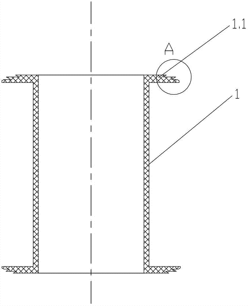
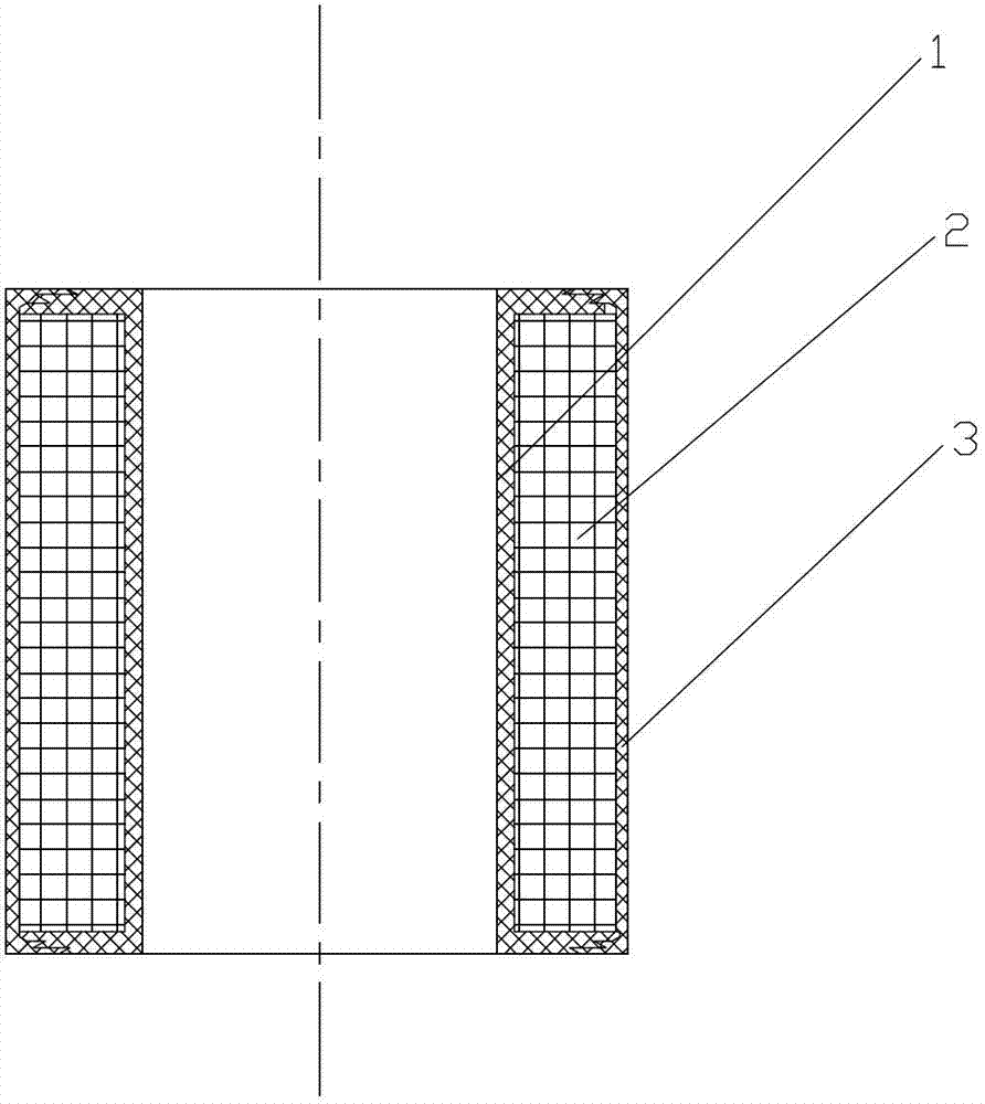
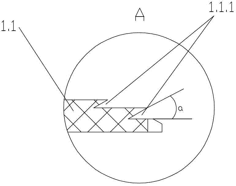
[0021] Such as figure 1 , figure 2 , image 3 As shown, the electromagnet bobbin of the present invention includes a bobbin body 1 with a central hole, two ends of the bobbin body 1 are respectively provided with radial protruding rings 1.1, and the outer wall of each radial protruding ring 1.1 At least one radial annular groove 1.1.1 is provided.

[0022] The number of said annular grooves 1.1.1 in this embodiment is two and distributed axially.

[0023] The radial convex ring 1.1 is provided with two steps, and each annular groove 1.1.1 is provided on a corresponding step.

[0024] The included angle a between the side wall and the bottom surface of the annular groove 1.1.1 is 20-70 degrees, that is to say, the single side cross section of the annular groove 1.1.1 is triangular.

[0025] The included angle a between the side wall and th...


PUM


Abstract

The invention discloses an electromagnet coil framework which comprises a coil framework body (1) with a central hole, wherein the two ends of the coil framework body (1) are respectively provided with radial convex rings (1.1); and the outer side wall of each radial convex ring (1.1) is provided with at least one radial annular groove (1.1.1). According to the electromagnet coil framework, the probability of entering water into the coil can be reduced, and the protection level is high.

Description

technical field [0001] The invention relates to the technical field of electromagnets, in particular to an electromagnet coil skeleton suitable for various liquid valves. Background technique [0002] The electromagnet mainly includes three parts: a coil, an iron core and an armature. The iron core is generally stationary, and the coil is mounted on the iron core. When the coil is energized, the iron core and the armature are magnetized and become two magnets with opposite polarities, thereby causing the armature to reciprocate. [0003] The electromagnet coil frame is used for winding coils, and the electromagnet coil frame includes a coil frame body with a central hole, and two ends of the coil frame body are respectively provided with radial protruding rings. After the electromagnet is assembled, the radial protruding rings at both ends of the coil bobbin are respectively tightly fitted and sealed with the electromagnet housing. There are sealing rings. There is followi...

Claims


Application Information

Patent Timeline
Patent Type & Authority Applications(China)
IPC IPC(8): H01F7/08H01F7/126H01F5/00
Inventor 刘晓林陈华林陈晓齐
Owner 宁波市鄞州通力液压电器厂
Why Eureka
Try Eureka