
Integrated lifting film evaporation device

A technology of evaporation device and lifting film, applied in evaporation, chemical instruments and methods, separation methods, etc., can solve the problems of affecting evaporation effect, low material recovery rate, short material evaporation time, etc., to improve gas-liquid separation efficiency, material High recycling rate and good material evaporation effect

Active Publication Date: 2015-01-14
安徽国孚环境科技股份有限公司
View PDF7 Cites 0 Cited by
  • Summary
  • Abstract
  • Description
  • Claims
  • Application Information

AI Technical Summary

Problems solved by technology

However, in the long-term industrial practice, their respective shortcomings are also exposed one by one. For example, both of them have the disadvantage of too short material evaporation time in the process, which greatly affects the evaporation rate of the finished product, which directly causes the low material recovery rate. , reducing the economic benefits of the enterprise
In addition, in the existing falling film evaporation process, when the material descends and evaporates along the tube wall, the uneven distribution and poor continuity of the film on the tube wall surface also affect the evaporation effect.

Method used


Image

  • Integrated lifting film evaporation device
  • Integrated lifting film evaporation device
  • Integrated lifting film evaporation device

Examples


specific Embodiment approach

[0029] One side of the upper tube plate 24 of the present invention is provided with an exhaust hole 13 for exhausting gas in the cavity.

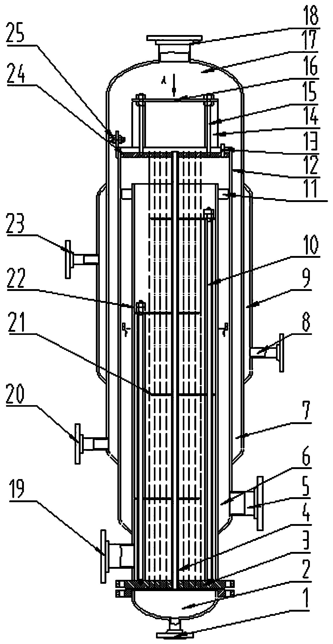
[0030] During operation, the heated heat transfer oil is circulated into the first heat transfer oil chamber 6 and the second heat transfer oil chamber 9, and then the pumped bubble point material enters the feed chamber 2 through the feed valve 1, and the material is evenly distributed in the feed chamber 2. Introduced into the evaporating tube bundle 4, the rising high-temperature airflow simultaneously drives the material to form a film along the tube wall of the evaporating tube bundle 4, and the high-temperature heat transfer oil infiltrated outside the evaporating tube bundle 4 continues to heat the material until it forms a gas-liquid mixture, and the high-temperature gas-liquid mixture is discharged Afterwards, it continuously impacts the circular plate 16 set on the top; a large amount of foam generated during the impact process is...


PUM


Abstract

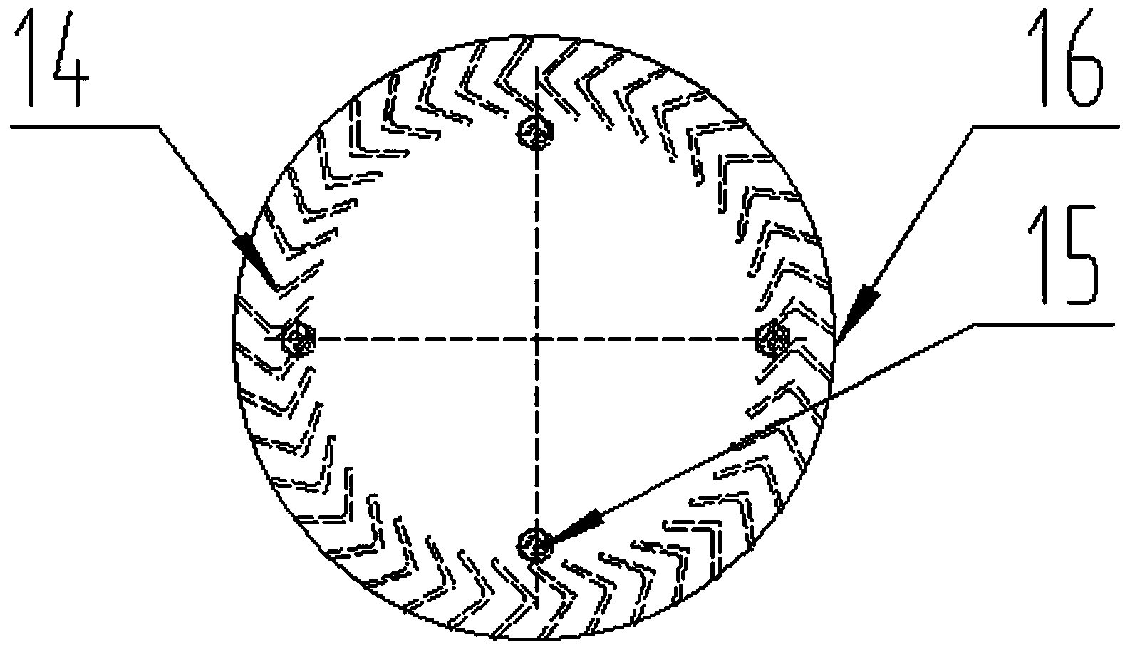
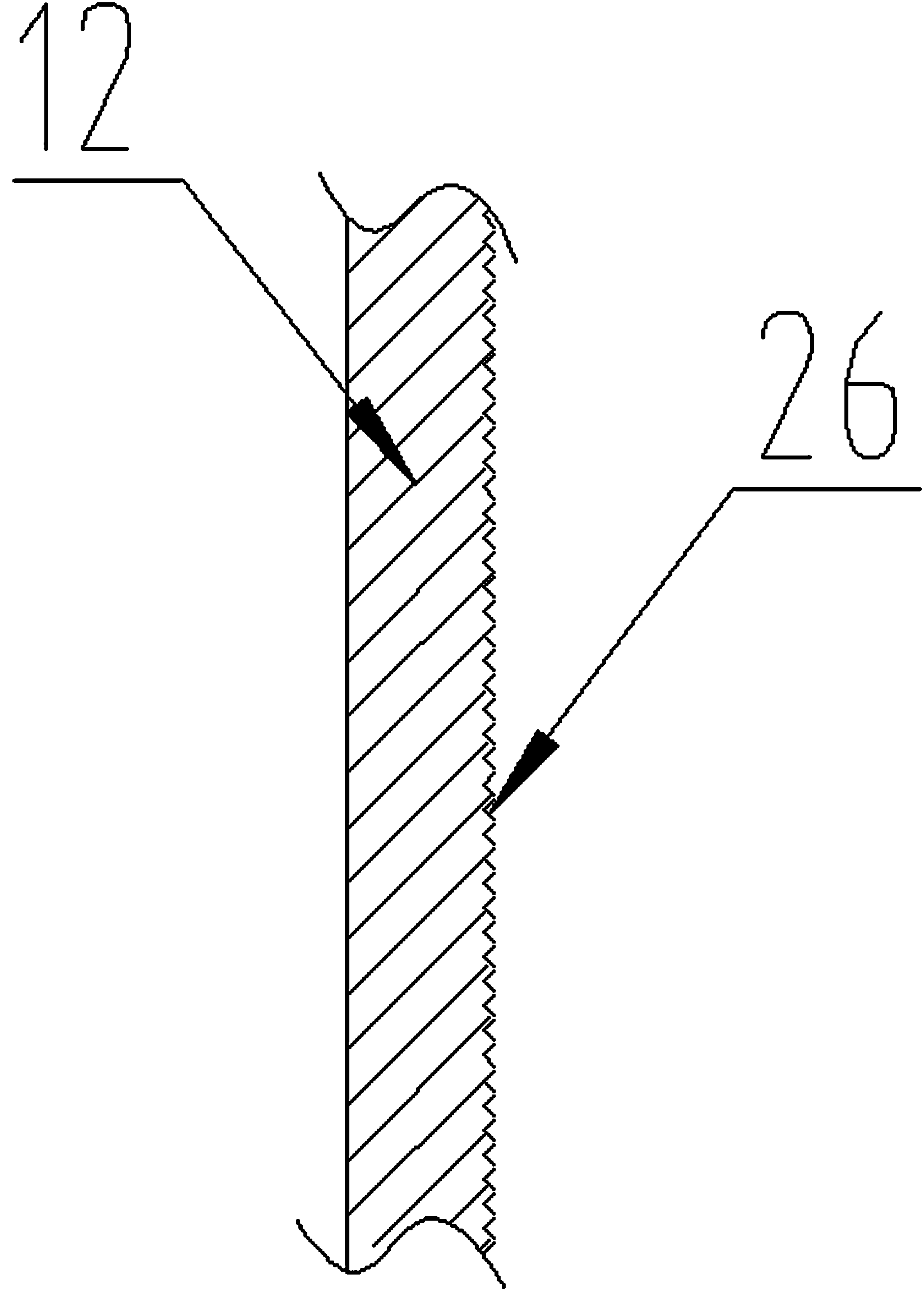
The invention relates to an integrated lifting film evaporation device which comprises a feed cavity with a feed valve, wherein a first heat conduction oil cavity with multiple evaporation tube bundles inside is formed above the feed cavity; the first heat conduction oil cavity is externally wrapped with an inverted material cavity and positioned by a support plate; an upper tube plate and a lower tube plate are fixed at the two ends of each evaporation tube bundle respectively; a corresponding circular plate is arranged on the top of the upper tube plate through a bracket; multiple baffle plates are fixed in the first heat conduction oil cavity through a distance rod; a discharge valve is arranged on one side of the material cavity, and a waste gas cavity and a gas-phase outlet are formed in the top; herringbone gas guide grids are uniformly distributed between the upper tube plate and the circular plate; a jacket is arranged around the evaporation tube bundles in the first heat conduction oil cavities; a positioning plate is arranged between the jacket and the inner tube wall of the first heat conduction oil cavity; a thread is arranged on the outer tube wall of the first heat conduction oil cavity wrapped by the material cavity; and the material cavity is externally wrapped by a second heat conduction oil cavity. The integrated lifting film evaporation device provided by the invention has the advantages of simple structure, efficient material evaporation and high recovery rate, remarkably reduces unit energy consumption and increases the economic benefits of an enterprise.

Description

technical field [0001] The invention relates to a device for liquid-liquid separation using an evaporation method, in particular to an integrated lifting film evaporation device. Background technique [0002] Rising film and falling film evaporators are used in a wide range of applications in the chemical industry and each has its own advantages. Among them, the rising film evaporator has the advantages of small footprint, low cost, strong operation controllability, and compact structure; the falling film evaporator has the advantages of high heat transfer coefficient, good thermal conductivity, easy adjustment and control, convenient and reliable, etc. However, in the long-term industrial practice, their respective shortcomings are also exposed one by one. For example, both of them have the disadvantage of too short material evaporation time in the process, which greatly affects the evaporation rate of the finished product, which directly causes the low material recovery ra...

Claims


Application Information

Patent Timeline
Patent Type & Authority Patents(China)
IPC IPC(8): B01D1/22
Inventor 李书龙
Owner 安徽国孚环境科技股份有限公司
Learn More