
Apparatus having negative dot pattern used in machining thin light guide plate

A processing device and light guide plate technology, which is applied in metal processing, light guide, optics, etc., can solve the problems of different processing depth, truncation, and defects of bending parts, and achieve the effects of reducing defects, improving quality, and maintaining processing depth

Inactive Publication Date: 2012-11-07
IST KOREA
View PDF6 Cites 5 Cited by
  • Summary
  • Abstract
  • Description
  • Claims
  • Application Information

AI Technical Summary

Problems solved by technology

However, if the light guide plate is a thin plate, if a scraper with multiple serrations is used for processing, it will bend at the position of the multiple serrations that are pressed and cause defects.
[0011] Moreover, the surface of the thin-plate light guide plate itself has been bent before processing, so if it is formed by ordinary scraping, it cannot overcome the height difference due to the bend, and the depth of the bent part will be increased. Different, or if the bending of the thin plate protrudes, it will be cut off when engraving and cause defects
[0012] In addition, since a plurality of serrations are processed at a time, the impact of processing is transmitted to the thin plate-type light guide plate at one time, so that bending occurs during processing deformation, and the processing depth of the curved part is different or cut off.

Method used


Image

  • Apparatus having negative dot pattern used in machining thin light guide plate
  • Apparatus having negative dot pattern used in machining thin light guide plate
  • Apparatus having negative dot pattern used in machining thin light guide plate

Examples


Embodiment Construction

[0064] Hereinafter, embodiments of the present invention will be described in detail with reference to the accompanying drawings in order to facilitate the implementation of the present invention by those skilled in the technical field of the present invention. However, the present invention can be embodied in various forms, and is not limited to the embodiments described here. The same symbols are used in similar parts of the description.

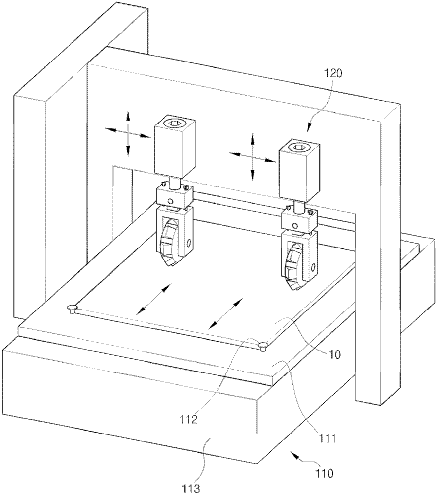
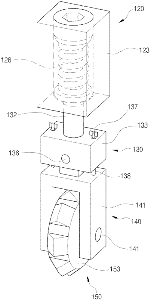
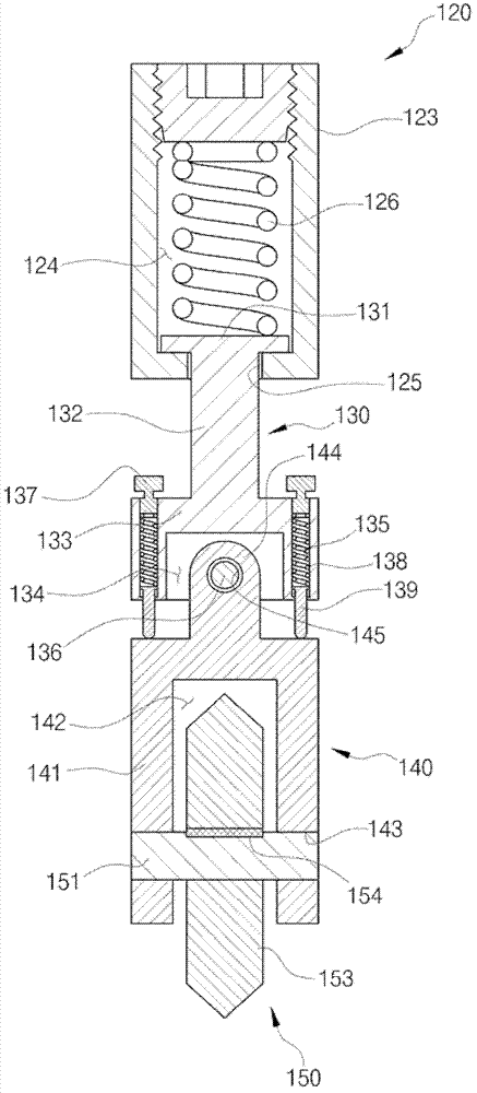
[0065] figure 1 It is a working state diagram illustrating the processing state of the thin plate type light guide plate processing device for imprinting small dot images of engraved intaglio according to an embodiment of the present invention; figure 2 engraved for illustration figure 1 A cross-sectional view of the main part of the thin plate-type light guide plate processing device for engraving small dot images; image 3 engraved for illustration figure 1 A cross-sectional view of the main part of the thin-plate type light guide p...


PUM


Abstract

An apparatus having a negative dot pattern used in machining a light guide plate. The apparatus includes a machining table unit disposed under the light guide plate, a drive unit disposed over the machining table unit, a plurality of adjustment units disposed over the light guide plate, a plurality of machining support units disposed over the light guide plate, and a plurality of machining units disposed over the light guide plate. When each machining unit has reached a machining position by being transported in transverse and vertical directions above the light guide plate by the drive device, each machining unit engraves dots while the light guide plate is being carried in the machining direction. After the light guide plate is machined, the drive device is transported to an upper position and to a position where next dots are intended to be engraved, and the next dots are sequentially engraved.

Description

technical field [0001] The present invention relates to a thin plate type light guide plate processing device for imprinting engraved small dot images. Background technique [0002] Generally, a display is a device that outputs an image based on an image signal. Displays such as liquid crystal displays (LCD, Liquid Crystal Display) have a color panel that outputs RGB colors. Since the color panel itself does not emit light, a backlight module that illuminates the color panel is provided to output images. [0003] A conventional backlight module includes a light source body for irradiating light to a display to generate a light source, and a light refraction device for uniformly supplying the generated light to a flat panel through refraction. The light refraction device further includes a light guide plate having a refractable image that refracts light from the light source body, and a light adjustment device that diffuses the light refracted by the light guide plate and ad...

Claims


Application Information

Patent Timeline
Patent Type & Authority Applications(China)
IPC IPC(8): B23D79/00
CPCG02B6/0065G02B6/0036Y10T83/037G02B6/00G02F1/1335B26D3/06G02F1/13
Inventor 许奉九
Owner IST KOREA
Learn More