
Electromagnetically-controlled driving device of engine cooling fan and implementation method of electromagnetically-controlled driving device

A technology of engine cooling and electromagnetic control, which is applied in the direction of engine cooling, engine components, machines/engines, etc. It can solve problems such as broken radiators, broken fan blades, increased relative slip between belts and wheels, etc., and achieves high control accuracy , Simple structure, fast response effect

Active Publication Date: 2012-11-07
XUELONG GRP
View PDF7 Cites 14 Cited by
  • Summary
  • Abstract
  • Description
  • Claims
  • Application Information

AI Technical Summary

Problems solved by technology

If the fan hub is directly rigidly connected to the rotating shaft, this vibration will be directly transmitted to the rotating shaft, which in turn affects the vibration of the entire engine front accessory drive system
When the vibration is severe, the fan blades may break and the radiator may be damaged, thus affecting the reliability of the engine.
In addition, the high-speed rotating fan has a large equivalent moment of inertia. If the fan hub is directly rigidly connected to the rotating shaft, when the engine suddenly decelerates or stops, the fan will still rotate at a relatively high speed, which will increase the relative friction between the belt and the wheel. Sliding, which will increase the wear of the belt, generate noise and other problems

Method used


Image

  • Electromagnetically-controlled driving device of engine cooling fan and implementation method of electromagnetically-controlled driving device
  • Electromagnetically-controlled driving device of engine cooling fan and implementation method of electromagnetically-controlled driving device
  • Electromagnetically-controlled driving device of engine cooling fan and implementation method of electromagnetically-controlled driving device

Examples


Embodiment 1

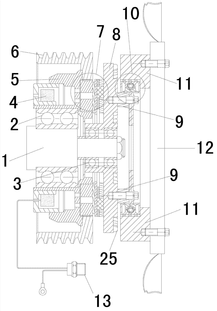
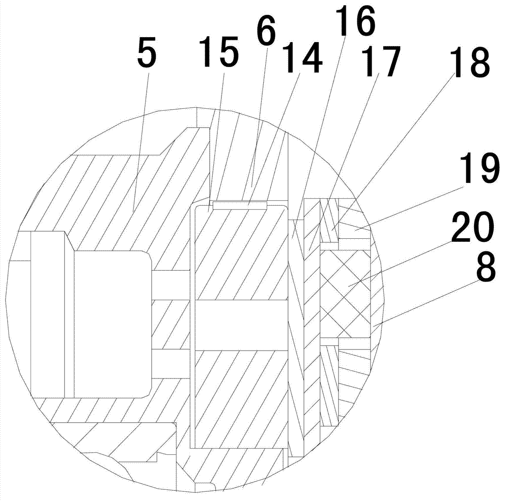
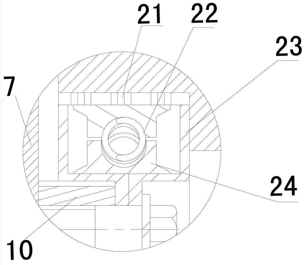
[0040] Such as Figure 1~3 As shown, an electromagnetically controlled engine cooling fan driving device includes a first bearing 2 and a second bearing 3 sleeved on a shaft 1, a coil 4 is sleeved outside the first bearing 1, and a rotor 5 is provided outside the coil 4, and the rotor 5. A belt pulley 6 is provided on the outside. A fan nonlinear speed regulation module 7 is arranged inside the belt pulley 6 and on the outer end surface of the rotor 5. A driven disk 8 is arranged on the outer surface of the fan nonlinear speed regulation module 7. The driven disk 8 is set on the second bearing 3. Above, the outer end of the driven disc 8 is provided with a mounting flange 9, one end of the mounting flange 9 is fixed to the one-way clutch decoupling wheel 10, and the other end of the one-way clutch decoupling wheel 10 is fixed to the fan mounting flange 11 , the fan mounting flange 11 is connected to the fan 12 , and the coil 4 is connected to the electronic control element 13 ...


PUM


Abstract

The invention discloses an electromagnetically-controlled driving device of an engine cooling fan. The electromagnetically-controlled driving device comprises a shaft, a first bearing, a second bearing, a coil, a rotor, a belt pulley, a fan nonlinear speed regulation module, a driven disc, a mounting flange, a one-way clutch decoupling wheel, a fan and an electronic control element. The invention further provides an implementation method of the electromagnetically-controlled driving device of the engine cooling fan. The problems of proneness to relative slip, complexity in structure, proneness to high-temperature failure and fan blade breakage, poor engine working reliability, high belt wear, high produced noise and the like in the prior art are solved, and the electromagnetically-controlled driving device of the engine cooling fan has the advantages of simple structure, high control precision, fast response, low vibration, low noise, nonlinear speed regulation, vibration reduction and the like.

Description

technical field [0001] The invention relates to the heat management system technology of an automobile engine, in particular to an electromagnetically controlled engine cooling fan driving device and a realization method thereof. Background technique [0002] According to relevant research data, 5-10% of the energy of a car engine is consumed by the cooling fan of the engine. The energy lost on the cooling fan includes: (1), vibration loss during fan operation; (2), friction loss during fan operation, etc. The electromagnetically controlled one-way clutch decoupling wheel of the engine cooling fan can well solve the vibration problem of the fan during operation; the nonlinear speed regulation module can adjust the speed of the engine cooling fan according to the engine working conditions to save energy. Considering the energy saving of the car, the car cooling fan should be based on the heat load conditions of the car engine. On the one hand, the fan rotates when the heat l...

Claims


Application Information

Patent Timeline
IPC IPC(8): F01P7/04F04D27/00
Inventor 贺频艳上官文斌段耀龙曾祥坤陈强胡惠祥
Owner XUELONG GRP
Learn More