Acoustic sensor and microphone

A sound sensor and diaphragm technology, applied in the direction of sensors, microphone structure associations, loudspeakers, etc., can solve the problems of reducing the size and difficulty of microphones

Active Publication Date: 2012-11-07
MMI SEMICON CO LTD
View PDF6 Cites 19 Cited by
  • Summary
  • Abstract
  • Description
  • Claims
  • Application Information

AI Technical Summary

Problems solved by technology

[0017] In the microphone of Patent Document 2, it has been difficult so far to effectively improve the signal-to-noise ratio in reality due to the occurrence of changes in the sensitivity and other sound characteris

Method used


Image

  • Acoustic sensor and microphone
  • Acoustic sensor and microphone
  • Acoustic sensor and microphone

Examples


no. 1 example

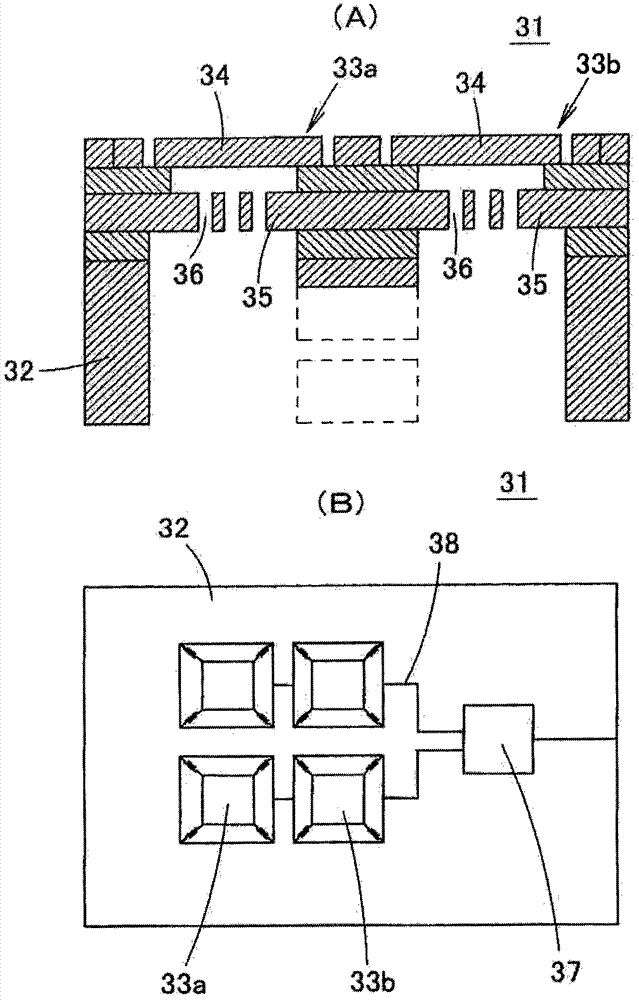
[0083] The structure of the sound sensor in the example 1 of the present invention will refer to the appended Figures 4 to 6 Be explained. attached Figure 4 is a sectional view of the acoustic sensor 41 in the first embodiment. attached Figure 5 is a plan view of the acoustic sensor 41 . attached Figure 6 is a plan view of a state where the cover portion 44 is removed from the acoustic sensor 41 .

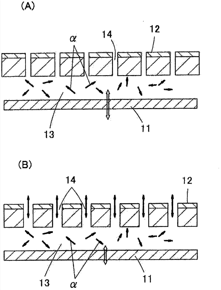
[0084] The acoustic sensor 41 is a capacitive element produced using MEMS technology. Such as Figure 4 As shown, in the acoustic sensor 41, the diaphragm 43 (vibrating electrode plate) is placed on the top surface of the silicon substrate 42 (semiconductor substrate) through a fixture 46, and the cover part 44 is fixed on it through a small air gap 50 (empty). top.

[0085] In the silicon substrate 42 made of single crystal silicon, a rear chamber 45 (hollow portion) penetrating from the front surface to the rear surface is opened. The inner peripheral surface of the ...

no. 2 example

[0138] Figure 12 is a plan view of the acoustic sensor 61 in Embodiment 2 of the present invention. Figure 13 It is a plan view of a state of the acoustic sensor 61 after the cover portion 44 is removed.

Embodiment 2

[0140] The acoustic sensor 61 in the second embodiment is a diaphragm 43 which is divided on it, and the area number is more than that of the acoustic sensor 41 in the first example. Even when the number of slits 47 is increased to increase the number of divided regions of the diaphragm 43 in this way (the shape and size of each diaphragm 43a, 43b, . The signal-to-noise ratio of the acoustic sensor 61 is feasible. In addition, as the number of divided regions of the diaphragm 43 increases, the effect of increasing the S / N ratio of the acoustic sensor 61 by reducing its noise increases accordingly.


PUM

PropertyMeasurementUnit
Widthaaaaaaaaaa

Abstract

An acoustic sensor capable of improving the sensor S/N ratio, without impeding reduction in sensor size is provided. A back chamber (45) opens at the top and bottom to a silicon substrate (42). A thin-film diaphragm (43) which serves as a movable electrode plate is formed on the upper surface of the substrate (42) so as to cover the back chamber (45). Back plates (48) are fixed to the upper surface of the substrate (42) so as to cover the diaphragm (43) and fixed electrode plates (49) are disposed on the lower surface of the back plates (48). In addition, the diaphragm (43) is divided into a plurality of areas by a slit (47), and a plurality of capacitors (acoustic sensing sections) (60a, 60b) connected in parallel are configured by each of the plurality of divided diaphragms (43a, 43b) and the fixed electrode plates (49).

Description

technical field [0001] The invention relates to a sound sensor and a microphone. The present invention particularly relates to a capacitive acoustic sensor manufactured using Micro Electro Mechanical System (MEMS) technology or micro-mechanical technology. The invention further relates to a microphone using the acoustic sensor. Background technique [0002] Microphones are found in a variety of devices, such as mobile phones and integrated circuit (IC) recorders. An acoustic sensor equipped in such a microphone is required to have an improved signal-to-noise ratio and a reduced size. [0003] As a method of improving the signal-to-noise ratio of the acoustic sensor, first, there must be a method of increasing the sensitivity of the acoustic sensor. In order to improve the sensitivity of this capacitive acoustic sensor, one method that can be used is to widen the area of ​​the diaphragm, and the other is to reduce the elastic properties of the diaphragm to increase t...

Claims


Application Information

Patent Timeline
IPC IPC(8): H04R19/04
CPCH04R19/04H04R2201/003H04R7/06H04R19/005H04R1/04H04R2410/03H01L29/84B81B3/00H01L2224/48137H01L2924/15151H01L2924/16152G01H11/00G01H15/00
Inventor 笠井隆
Owner MMI SEMICON CO LTD
Why Eureka
Try Eureka