Impact screw drilling tool

A screw drilling tool and percussion technology, which is applied in the direction of drilling tools, drilling equipment, earthwork drilling, etc., can solve the problems of easy damage and short service life of cutting teeth, and achieve the effect of improving service life, improving efficiency and realizing convenience

Inactive Publication Date: 2012-11-14
熊继有 +1
View PDF8 Cites 26 Cited by
  • Summary
  • Abstract
  • Description
  • Claims
  • Application Information

AI Technical Summary

Problems solved by technology

[0023] The purpose of the present invention is to provide a percussive screw drilling tool, which solves the problem in the prior art that the scr

Method used


Image

  • Impact screw drilling tool
  • Impact screw drilling tool
  • Impact screw drilling tool

Examples


Embodiment 1

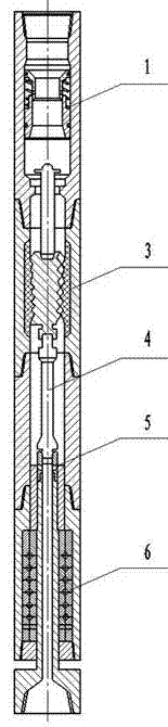
[0070] like figure 1 As shown, the impact screw drilling tool includes a bypass valve assembly 1, a motor assembly 3, a cardan shaft assembly 4 and a drive shaft assembly 6 connected in sequence, wherein the bypass valve assembly is mainly composed of a valve body , valve core, spring and sieve plate, the motor assembly is mainly composed of the stator housing and the rotor, the cardan shaft assembly is mainly composed of the cardan shaft housing and the cardan shaft, and the transmission shaft assembly is mainly composed of the transmission shaft housing , a hollow transmission shaft, a thrust bearing group and a radial bearing group; a flow adjustment assembly 5 is arranged between the transmission shaft assembly 6 and the cardan shaft assembly 4, and the upper end of the flow adjustment assembly is in contact with the universal joint The shaft is connected, and the lower end is connected with the transmission shaft.

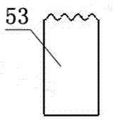
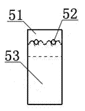
[0071] like figure 2 and image 3 As shown, the flow...

Embodiment 2

[0074] like Figure 4 and Figure 5 As shown, the difference between this embodiment and Embodiment 1 is that a hydraulic pressurization assembly 2 is provided between the bypass valve assembly 1 and the motor assembly 3, and the hydraulic pressurization assembly is in the form of the upward movement of the piston, mainly composed of a hollow Mandrel 21, upper and lower shell 22, sealing ring 23, disc spring group 24 and pipe plug 25; the upper end of the mandrel is threaded and the lower end of the bypass valve assembly is threaded, and the lower part is located in the shell and the middle Cooperate with the inner side of the upper part of the shell, there is a shoulder between the lower part and the middle part outside the mandrel, and the wall thickness of the lower part is 1 / 3~1 / 2 of the wall thickness of the middle part, and the lower end is connected with the pipe plug through threads, and the disc spring assembly The lower part of the mandrel is sleeved between the pip...

Embodiment 3

[0077] like Image 6 As shown, the difference between this embodiment and embodiment 2 is that the hydraulic pressurization assembly 2 is arranged on the upper end of the bypass valve assembly 1, the lower end of the casing is connected with the upper end of the bypass valve assembly through threads, and the thread at the upper end of the mandrel is used for Connect with external agencies. This setting method is used for deep drilling. Since the position of the hydraulic pressurization assembly is high, it can reduce the impact of the damaged rock formation on it, and increase the impact force generated by the drilling fluid in the screw drilling tool, and then Improve the rock-breaking effect and prolong the service life.


PUM


Abstract

The invention discloses an impact screw drilling tool, and belongs to a well drilling technology and the impact screw drilling tool can be used for solving the problems that the screw drilling tool instantly produces an impact force and the cutting tooth of a drill bit is easy to damage in the prior art. The impact screw drilling tool comprises a bypass valve assembly, a motor assembly, a universal shaft assembly and a transmission shaft assembly which are sequentially connected, wherein the bypass valve assembly mainly consists of a valve body, a valve core, a spring and a sieve plate, the motor assembly mainly consists of a stator shell and a rotor, the universal shaft assembly mainly consists of a universal shaft shell and a universal shaft, and the transmission shaft assembly mainly consists of a transmission shaft shell, a hollow transmission shaft, a thrust bearing set and a radial bearing set; and a flow control assembly is arranged between the transmission shaft assembly and the universal shaft assembly. According to the screw drilling tool disclosed by the invention, on the basis of the original performance, the flow control assembly produces a flexible impact force, the rock-breaking efficiency of the drill bit is improved, the mechanical penetration rate is improved, the service life is greatly prolonged, and the application range of the screw drilling tool disclosed by the invention is widened by utilizing hydraulic power pressurizing assemblies at different positions.

Description

technical field [0001] The invention relates to the fields of drilling engineering hydraulic impactors and downhole power tools, in particular to an impact screw drilling tool. Background technique [0002] How to increase the drilling speed is currently a technical problem being studied by countries all over the world. In particular, with the increase of well depth, the loss of hydraulic power along the way increases, the available water energy of the drill bit at the bottom of the well decreases sharply, and the ability of hydraulic rock breaking and rock cleaning is weakened, resulting in deep wells. Problems such as low drilling speed, rapid drill bit wear and serious sticking; in addition, in order to improve oil production efficiency, more and more attention has been paid to horizontal wells, lateral wells, extended-reach wells, and slave wells, and the current wellbore is becoming more and more irregular , friction and torque are large, sliding drilling is difficult,...

Claims


Application Information

Patent Timeline
IPC IPC(8): E21B6/00E21B11/00
Inventor 董学成熊继有魏小梅王国华
Owner 熊继有
Why Eureka
Try Eureka