
Circular polarization spiral antenna with high low elevation gain

A helical antenna and circularly polarized technology, applied in the directions of helical antennas, antennas, non-resonant long antennas, etc., can solve the problems of limited effect, increased volume and weight, and difficulty in meeting the index requirements, and achieves convenient debugging and compact structure. , the effect of simple structure

Active Publication Date: 2012-11-14
广州桑瑞科技有限公司
View PDF3 Cites 11 Cited by
  • Summary
  • Abstract
  • Description
  • Claims
  • Application Information

AI Technical Summary

Problems solved by technology

The microstrip antenna has a low profile, simple manufacture, and low cost. However, the performance of the pattern and axial ratio is slightly inferior to that of the helical antenna, and its lobe width is narrow, which is difficult to meet the higher index requirements in actual use.
[0004] The traditional helical antenna has a good upper hemispherical pattern and a wide lobe width, but the gain at low elevation angles is generally not high enough to meet relatively high index requirements
and direction Figure 1 Generally, it is adjusted through the spiral parameters, and these parameters will affect other performances of the antenna at the same time, sometimes it is difficult to balance and take into account, and the design process is cumbersome and time-consuming
[0005] In order to improve the low elevation gain, the easiest way is to change the shape and size of the floor, but the effect of this method is very limited, and it will bring the disadvantage of increased volume and weight
[0006] In addition, the use of conical helical antennas can increase the beam width and increase the gain at low elevation angles, but the range of improvement is also very limited, and there are disadvantages of large volume and complex structure

Method used


Image

  • Circular polarization spiral antenna with high low elevation gain
  • Circular polarization spiral antenna with high low elevation gain
  • Circular polarization spiral antenna with high low elevation gain

Examples


Embodiment 1

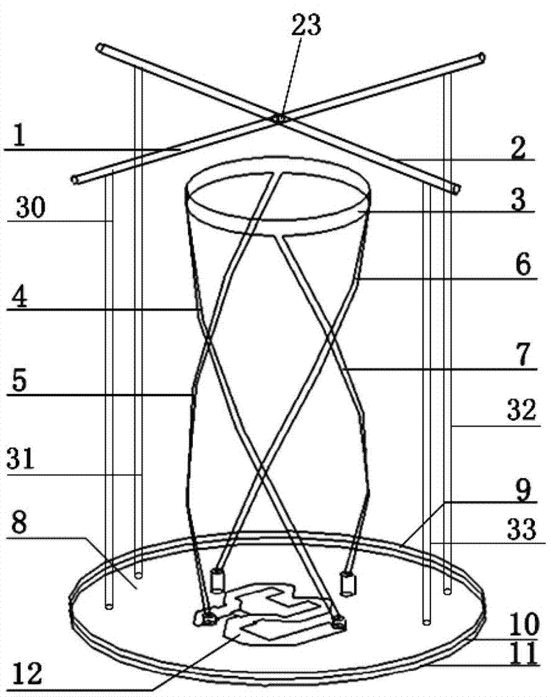
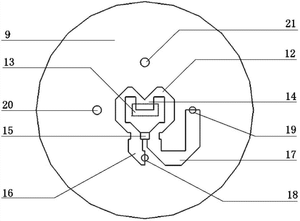
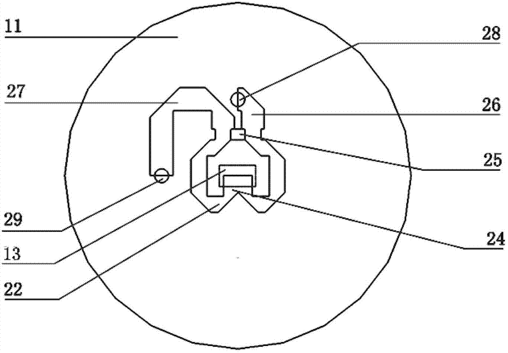
[0034] Such as figure 1 As shown, a circularly polarized helical antenna with high and low elevation angle gain in the present invention includes a cylindrical helical antenna radiator, a cross-shaped cross-shaped dipole parasitic unit 23 and a power-division phase-shifting broadband microstrip feed network 8, and the cross-shaped cross-shaped dipole The parasitic unit 23 is located above the cylindrical helical antenna radiator, and the distance between the cross-shaped crossed oscillator parasitic unit 23 and the cylindrical helical antenna radiator is 0.25 wavelengths, and the power division phase-shifting broadband microstrip feed network 8 is located at The bottom of the cylindrical helical antenna radiator is connected with the bottom of the cylindrical helical antenna radiator.

[0035] The cylindrical helical antenna radiator includes four metal helical arms 4~7, and the four metal helical arms 4~7 are placed orthogonally in space along the side of the cylinder and wo...

Embodiment 2

[0042] Except for the distance between the parasitic unit of the cross-shaped crossed oscillator and the radiator of the cylindrical helical antenna, and the length of the oscillator, other features of this embodiment are the same as those of Embodiment 1.

[0043] In this embodiment, the distance between the parasitic unit of the cross-shaped cross oscillator and the radiator of the cylindrical helical antenna is 0.4 wavelengths.

[0044] The vibrator of this embodiment is used as an antenna director, the length is 0.42 wavelengths, and its right-handed gain curve is as follows Image 6 shown.

Embodiment 3

[0046] Except for the length of the vibrator in this embodiment, other features are the same as those in Embodiment 1.

[0047] The vibrator of this embodiment is used as an antenna reflector with a length of 0.7 wavelengths, and its right-handed gain curve is as follows Figure 7 shown.


PUM


Abstract

The invention discloses a circular polarization spiral antenna with high low elevation gain, which comprises a cylindrical spiral antenna radiator, a cross-shaped cross vibrator parasitic unit and a power division phase shift broadband microstrip feed network. The power division phase shift broadband microstrip feed network is positioned below the cylindrical spiral antenna radiator and is connected with the bottom of the cylindrical spiral antenna radiator; and the cross-shaped cross vibrator parasitic unit is positioned above the cylindrical spiral antenna radiator, and comprises two vertical vibrators, wherein when the vibrators are used as antenna directors, the length of the vibrators is less than half wavelength; and when the vibrators are used as antenna reflectors, the length of the vibrators is greater than the half wavelength. The antenna has the advantages of wide frequency band, excellent directional diagram performance, high low elevation gain, compact structure and light weight.

Description

technical field [0001] The invention relates to a circularly polarized helical antenna, in particular to a circularly polarized helical antenna with high and low elevation angle gain. Background technique [0002] At present, the application of global positioning and navigation systems is becoming more and more extensive. China's Beidou second-generation system has basically covered the Asia-Pacific region and is expected to cover the whole world in the next ten years. Circularly polarized antennas play a vital role in this system. effect. According to the positioning principle, the low elevation signal close to the ground contributes the most to the positioning accuracy, while the zenith signal is easy to accept but does not contribute much to the positioning accuracy. With the improvement of positioning accuracy requirements, the antenna is generally required to have a higher low-elevation gain, especially for the Beidou system, which has relatively few satellites, and pu...

Claims


Application Information

Patent Timeline
Patent Type & Authority Applications(China)
IPC IPC(8): H01Q11/08H01Q13/08H01Q1/36
Inventor 褚庆昕林伟鑫潘泽坤
Owner 广州桑瑞科技有限公司
Learn More