Power supply control device and power supply control system

A power control device and control terminal technology, which is applied to circuit devices, battery circuit devices, current collectors, etc., can solve the problem of many pin resources, and achieve the effects of saving pin resources, improving utilization, and saving system costs

Active Publication Date: 2012-11-14
SG MICRO
View PDF4 Cites 9 Cited by
  • Summary
  • Abstract
  • Description
  • Claims
  • Application Information

AI Technical Summary

Problems solved by technology

[0007] The present invention provides a power supply control device and a power supply control system to solve the problem of more pin resources occupied by the power supply system in the related art

Method used


Image

  • Power supply control device and power supply control system
  • Power supply control device and power supply control system
  • Power supply control device and power supply control system

Examples


Embodiment 1

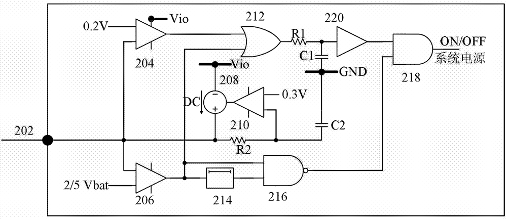
[0026] This preferred embodiment provides a power control device, figure 2 shows a preferred circuit diagram of the device, from figure 2 It can be seen from the figure that the power control device includes: a first input node 202 for inputting a control signal; a first comparator 204, the first input terminal of the first comparator 204 is connected to the first input node 202, and the first comparator The second input terminal of the comparator 202 is connected with the first low level, preferably, the size of the first low level is 0.2V, that is, the threshold voltage of the first comparator 202 is 0.2V, and the selected 0.2V threshold The voltage is that all CMOS IO circuits can guarantee to reach the low level; the second comparator 206, the first input terminal of the first comparator 204 is connected with the first high level, the second input terminal of the second comparator 206 is connected with the first The input node is connected. Preferably, the above-mention...

Embodiment 2

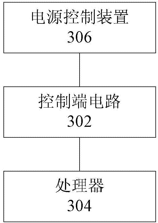
[0034] On the basis of the above-mentioned embodiment 1, this preferred embodiment provides a power control system, image 3 A preferred circuit structure diagram of the system is shown, and the system includes: a control terminal circuit 302, a processor 304, and a power control device 306 included in Embodiment 1, wherein the output terminals of the control terminal circuit 302 are respectively connected to the power supply control The first input node of the device 306 is connected to the second input node of the processor 304 for outputting different control signals.

[0035] This preferred embodiment also provides a preferred solution of the control terminal circuit 302, specifically, as Figure 4 As shown, the control terminal circuit includes: a battery 402 for providing the first voltage Vbat; a button 404, the first end of the button 404 is connected to the battery 402, wherein, when the button 404 is in a pressed state, the control terminal circuit is a power control...


PUM


Abstract

The invention provides a power supply control device and a power supply control system. The device comprises a first input node, a first comparator, a second comparator, a controlled source, an amplifier, an or logic gate circuit, a delay circuit, a first NAND logic gate circuit and a second NAND logic gate circuit. By the power supply control device and the power supply control system, the problem that a power supply system in the related technology occupies much pin resources is solved; the pin resources and the system cost are saved; and the utilization rate of pins is improved.

Description

technical field [0001] The invention relates to the field of power supplies, in particular to a power supply control device and a power supply control system. Background technique [0002] In electronic equipment, the power supply system is an essential component of the equipment, and the power supply system ensures the functions of opening, maintaining and closing the equipment. Existing power system designs such as figure 1 As shown, it includes the control terminal circuit, the main power supply system and the microprocessor of the powered system, wherein the control terminal circuit controls the output voltage; the main power supply system realizes the start, stop and maintenance of the equipment according to the output of the control terminal circuit; the powered system The microprocessor is used for detecting the state of the button on the circuit end of the control end and the output state of the power supply of the device. [0003] use figure 1 The power system sh...

Claims


Application Information

Patent Timeline
IPC IPC(8): H02J7/00
Inventor 谭磊
Owner SG MICRO
Why Eureka
Try Eureka