Conical nanostructures on substrate surfaces, in particular optical elements, methods for the production thereof and use thereof

A substrate surface and nanostructure technology, applied in the process for producing decorative surface effects, microstructure technology, microstructure devices, etc., can solve the problems of not being able to manufacture columnar and conical structures, and achieve the possibility of wide application Effect

Active Publication Date: 2012-11-14
MAX PLANCK GESELLSCHAFT ZUR FOERDERUNG DER WISSENSCHAFTEN EV
View PDF11 Cites 6 Cited by
  • Summary
  • Abstract
  • Description
  • Claims
  • Application Information

AI Technical Summary

Problems solved by technology

But this method cannot fabricate itself from SiO 2 or

Method used


Image

  • Conical nanostructures on substrate surfaces, in particular optical elements, methods for the production thereof and use thereof
  • Conical nanostructures on substrate surfaces, in particular optical elements, methods for the production thereof and use thereof
  • Conical nanostructures on substrate surfaces, in particular optical elements, methods for the production thereof and use thereof

Examples


Embodiment 1

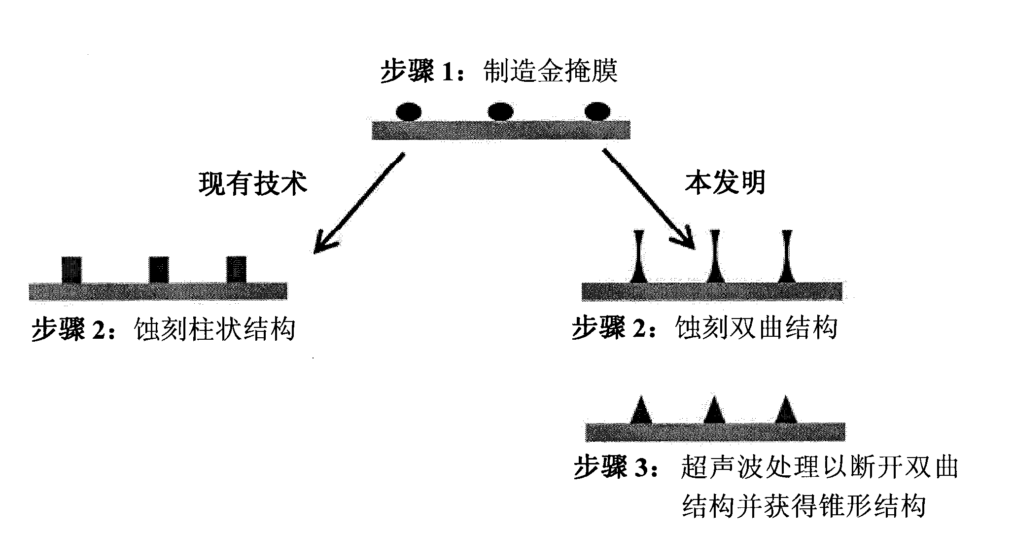
[0034] Creation of tapered nanostructures on substrates with gold nanoparticle alignment

[0035] 1. Provide the substrate surface

[0036] First, the surface of a substrate, such as quartz glass, is covered with gold nanoparticles in a defined arrangement by means of micellar nanolithography. In this step, the reports described in EP 1 027 157 B1, DE 197 47 815 A1 or DE 10 2007 017 032 A1 can be followed. The method involves depositing a micellar solution of a block copolymer such as Polystyrol(n)-b-Poly(2-vinyl-pyridin(m) in toluene) on a substrate, for example by dip coating, whereby the surface Forms an ordered membrane structure of polymer blocks. The micelles in solution contain gold salts, preferably HAuCl 4 , which were reduced to gold nanoparticles with the polymer film after deposition. The reduction can be carried out chemically with hydrazine, or with the aid of high-energy radiation such as electron radiation or light. The polymer film is preferably removed af...

Embodiment 2

[0052] Characterization of Nanostructures

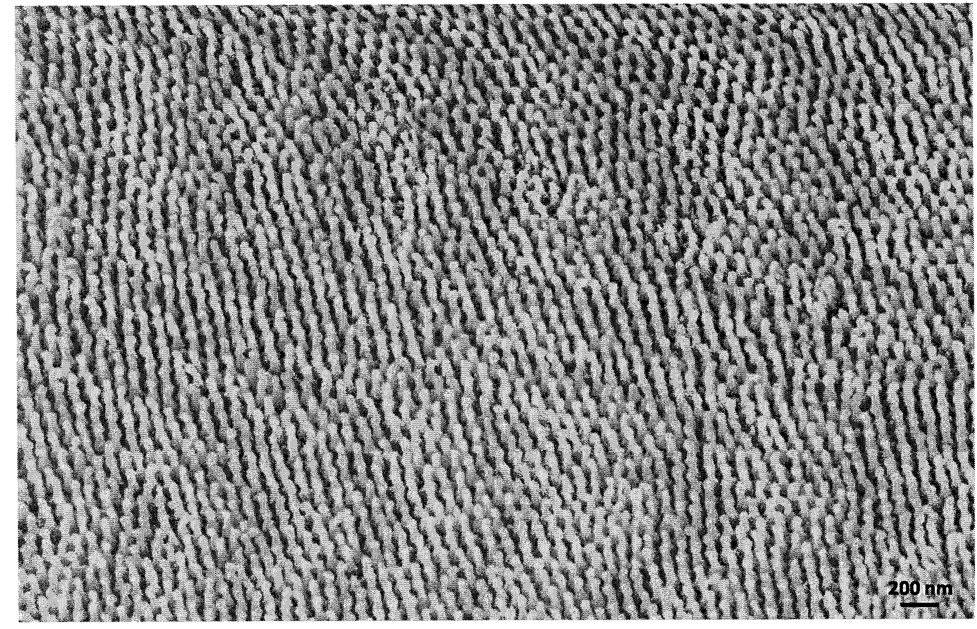
[0053] From the nanostructures obtained according to the invention and the nanostructures of the prior art, photographs were taken at different tilt angles using a scanning electron microscope.

[0054] Figure 2a Shown is a scanning electron micrograph of etched cylindrical nanostructures at a tilt angle of 20°, which was produced using a method similar to that described in DE 2007 014 538. The method was changed slightly (other etch chemistries, multiple etch steps) so that deeper structures could be produced. The etching conditions specifically called by the old method cannot produce structures below 120nm. The height of the pillars is about 250 nm and the diameter is about 50 nm. Its average distance is about 80nm. Figure 2b Shown is a magnified side view of the same structure at a 45° angle. Make scratches on the surface with the aid of a glass knife so that the shape can be seen at a glance.

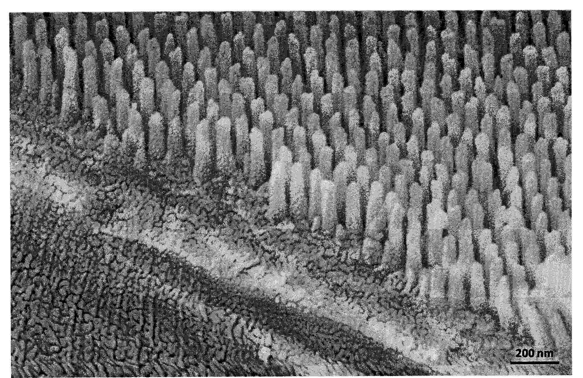
[0055] image 3 Shown is a...


PUM

PropertyMeasurementUnit
Heightaaaaaaaaaa
Heightaaaaaaaaaa

Abstract

The invention relates to conical structures on substrate surfaces, in particular optical elements, to methods for the production thereof and to the use thereof, in particular in optical devices, solar cells and sensors. The conical nanostructures according to the invention are suitable in particular for providing substrate surfaces having very low light reflection. The method according to the invention for producing conical nanostructures on substrate surfaces comprises at least the steps of: a) providing a substrate surface covered with nanoparticles; b) etching the substrate surface covered with nanoparticles to a depth of at least 100 nm, wherein the nanoparticles act as an etching mask and the etching parameters are set in such a way that hyperboloid structures are produced underneath the nanoparticles; c) breaking the hyperboloid structures in the region of the smallest diameter by exerting mechanical forces, wherein the structures remaining on the substrate surface have a conical shape which corresponds substantially to half a single-shell hyperboloid.

Description

technical field [0001] Partial reflection of light is always of concern when light hits eg air / glass or the opposite interface. At normal incidence on the glass plate, the two interfaces each reflect about 4% of the incident light. This value rises to about 5% with light incident at acute or obtuse angles. This partial reflection is a matter of concern for many applications, for example in optical elements such as lenses where as high a transmission as possible is desired. Background technique [0002] Reflection-reducing coatings consisting of thin films are commercially available. However, such coatings are expensive, their mechanical stability is generally unsatisfactory and their tolerances with respect to the angle of incidence are very low. Recently to solve this problem it has been proposed to coat the surface of optical elements with micro- and nanostructures, which are similar to Mottenaugen's structures and are therefore aptly also called Mottenaugen structures ...

Claims


Application Information

Patent Timeline
IPC IPC(8): B81C1/00
CPCB81B2203/0361B81B2207/056B81C1/00031Y10T428/24479
Inventor C·莫尔哈德C·帕霍尔斯基J·P·施帕茨
Owner MAX PLANCK GESELLSCHAFT ZUR FOERDERUNG DER WISSENSCHAFTEN EV
Why Eureka
Try Eureka