Hydrographic survey device for small water area

A hydrographic survey and water area technology, applied in surveying devices, open-air water source surveys, surveying and mapping, and navigation, etc., can solve problems such as unstable equipment data collection efficiency and complex mechanical structures

Inactive Publication Date: 2012-11-21
NORTHWESTERN POLYTECHNICAL UNIV
View PDF3 Cites 9 Cited by
  • Summary
  • Abstract
  • Description
  • Claims
  • Application Information

AI Technical Summary

Problems solved by technology

[0003] In order to avoid the shortcomings of the existing technology and overcome the problems of complex mechanical structure and unstab

Method used


Image

  • Hydrographic survey device for small water area
  • Hydrographic survey device for small water area
  • Hydrographic survey device for small water area

Examples


Embodiment 1

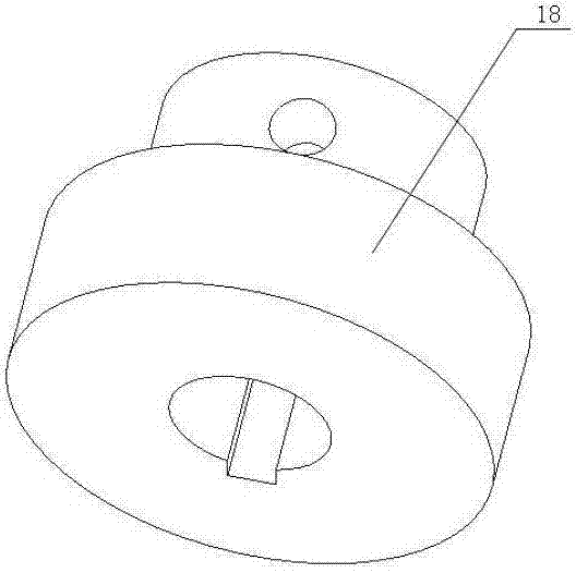
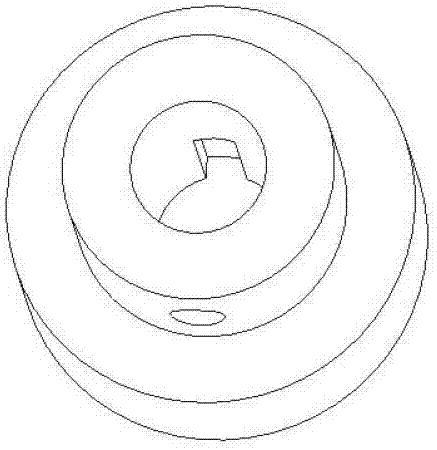
[0033] refer to figure 1 , figure 2 , image 3 The hydrological measuring equipment used in small water areas of the present invention is composed of a fixed mechanism 1, a transmission belt 2, a rope 3, a moving pulley frame 4, a suspension bracket 5, a guide cable 6, a base 7, a fixed plate 8, a tension bolt 9, and a support seat bolt 10. Fixed plate bolt 11, support seat 12, locking collar 13, pulley drive shaft 14, locking sleeve 15, handle 16, driving wheel 17, clutch 18, set bolt 19, main drive shaft 20, bearing end Cover 21, roller 22, bolt 23, control panel 24, splint 30, suspension frame 31, pulley pin shaft 32, drive belt driven wheel 33, bolt 34, steel beam 35, rolling bearing 36, circlip for hole 37, cotter pin 38, square hole sliding clutch 39, clutch set bolt 40 form. The fixing mechanism 1 is installed on the bank of the water area, and the suspension bracket 5 is fixedly installed on the opposite bank, and can also be installed above the water area accordin...

Embodiment approach

[0042] Figure 14 It is the second embodiment of the clutch between the pulley drive shaft and the main drive shaft of the present invention. The end of the pulley drive shaft and the main drive shaft is processed into a square shaft, and the square hole slip clutch 39 is installed on the pulley drive shaft , or installed on the end of the main drive shaft, it can slide on it. When the two shafts are connected in parallel, the sleeve slides to the middle position, and the set screw 40 of the square hole sliding clutch is tightened to prevent the sleeve from sliding. When the two shafts are separated, loosen the set screw 40 of the square hole sliding clutch, slide the sleeve to one end, and disengage from the other shaft end, so as to realize the independent movement of the two shafts. The suspension frame is fixedly connected to the steel beam through bolts 34, and the horizontal or vertical movement of the measuring device is realized through the transmission belt and the r...


PUM


Abstract

The invention discloses a hydrographic survey device for a small water area, characterized by arranging a fixed mechanism at the side of the water area, fixing a suspension support at the opposite side; a guiding steel rope is arranged between the fixed mechanism and the suspension support; a mobile pulley rack is driven to horizontally move by a driving wheel arranged on a driving belt of the fixed mechanism; the end of the rope is provided with a measurement sensor by the pulleys of the mobile pulley rack; and the rope is reeled or unreeled by rotating the rollers on the fixed mechanism to realize the vertical movement of the measurement sensor; a control disc controls a main transmission shaft and a belt wheel transmission shaft to individually or synchronously rotate by a clutch, and drives the measurement sensor to move horizontally at a constant depth underwater to measure the data of different positions of the fixed depth, or drives the measurement sensor to vertically move at a fixed position to measure the data of different depths. The invention has the advantages of simple structure, convenient usage and movement, safety, reliability, and high data acquisition efficiency, and can be suitable for different work environments of small reservoirs or ponds.

Description

technical field [0001] The invention relates to a hydrological measuring device used in small water areas, and belongs to the technical field of mechanical design, manufacture and testing. Background technique [0002] At present, the relatively mature hydrological equipment used in underwater data acquisition technology can be roughly divided into two types: one is mobile and the other is throwing fixed. The mobile hydrological data measurement equipment is installed on the bilge of the ship when it is in use, and reaches the designated position to be measured by the movement of the ship for data collection. Similar devices are suitable for use in large water areas, and are used in occasions where the specific measurement location is relatively random. The measurement mobility is high, but the corresponding measurement cost is also relatively high. In small waters, the use of this measuring device not only does not give full play to its outstanding mobility, but also incre...

Claims


Application Information

Patent Timeline
IPC IPC(8): G01C13/00
Inventor 张文杰谭小群周涛涛徐娅萍杨伟平孙刚峰周金芳
Owner NORTHWESTERN POLYTECHNICAL UNIV
Why Eureka
Try Eureka