Low dropout regulator

A technology of low-dropout linear and linear voltage regulators, which is applied in the direction of instruments, electrical variable adjustment, control/regulation systems, etc., to enhance pull-up and pull-down capabilities, improve output transient response, and achieve stability.

Inactive Publication Date: 2012-11-21
UNIV OF ELECTRONICS SCI & TECH OF CHINA
View PDF5 Cites 38 Cited by
  • Summary
  • Abstract
  • Description
  • Claims
  • Application Information

AI Technical Summary

Problems solved by technology

[0005] The purpose of the present invention is to solve the above-mentioned proble

Method used


Image

  • Low dropout regulator
  • Low dropout regulator
  • Low dropout regulator

Examples


Embodiment Construction

[0023] The present invention will be further elaborated below in conjunction with the accompanying drawings and specific embodiments.

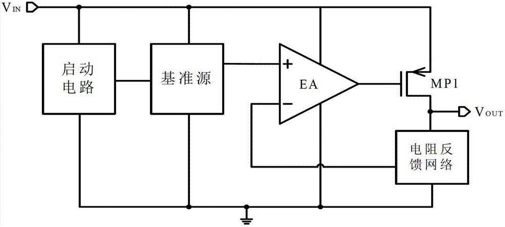
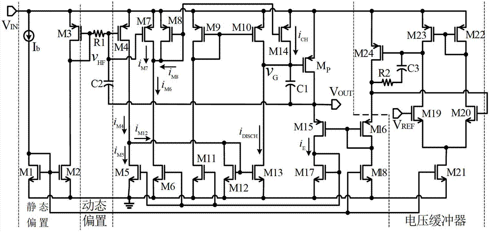
[0024] The structure diagram of the low dropout linear voltage regulator of the present invention is as follows figure 2 As shown, it specifically includes: the current subtraction circuit when the load composed of PMOS transistor M4 and NMOS transistor M5 jumps from light load to heavy load, the fast response path composed of PMOS transistor M7, M8, M14, and NMOS transistor M6, and the PMOS transistor M9 , M10, M15, M16, NMOS tubes M11, M12, M13, M17, M18 composed of a common gate error amplifier and power P tube Mp and compensation capacitor C1.

[0025] As a preferred option, figure 2 A realization form of a bias circuit is given, specifically including: current source Ib, NMOS transistors M1, M2, PMOS transistor M3, resistor R1 and capacitor C2, wherein, current source Ib, NMOS transistors M1, M2, PMOS transistor M3 The static bias is ...


PUM

PropertyMeasurementUnit
Capacitanceaaaaaaaaaa

Abstract

The invention discloses a low dropout regulator, comprising a current substraction circuit which consists of MOS (metal oxide semiconductor) tubes M4 and M5 and has a load hopping from a light load to a heavy load, a current substraction circuit which consists of M6 and M7 and has a load hopping from a heavy load to a light load, as well as a fast response pathway which consists of M7, M8 and M14 and has a load hopping from a heavy load to a light load. According to the LDO (low dropout regulator) disclosed by the invention, the bias current of an error amplifier is increased only when the circuit is transiently switched, thereby the output transient response is improved, and the quiescent current of the circuit at a steady state is ensured to be very low; when the load hops from the heavy load to the light load, the fast response pathway is increased, the bandwidth of a transient loop is expanded, the output transient characteristic is improved, and the magnitude of output spike voltage is reduced; and furthermore, when the LDO is in a steady state, only an EA main loop is involved in work, thereby the quiescent current of the LDO is not increased.

Description

technical field [0001] The invention belongs to the technical field of power supply management, and in particular relates to the design of an off-chip large-capacitance low-dropout linear regulator with fast load response. Background technique [0002] Low-dropout voltage regulators (Low-dropout voltage regulators, LDO) as a class of important circuits in power management chips are widely used due to their low cost, low output noise, simple circuit structure, and small chip area. The development of modern power management technology in the direction of SOC also puts forward new requirements for the performance of LDO: 1) lower power consumption, that is, smaller quiescent current; 2) better transient response, that is, better Compensation mode and topology; 3) Easy to integrate, that is, no off-chip large capacitors and overly complicated compensation circuits are required. [0003] Ordinary LDO circuits are generally composed of error amplifiers, voltage reference sources,...

Claims


Application Information

Patent Timeline
IPC IPC(8): G05F1/56
Inventor 明鑫王鑫谭林张晓敏周泽坤王卓张波
Owner UNIV OF ELECTRONICS SCI & TECH OF CHINA
Why Eureka
Try Eureka