
Automatic gain control for capacitive touch panel sensing system

A capacitive touch and touch panel technology, applied in gain control, amplification control, digital/coded signal control, etc., can solve the problems of complex touch position determination and limited effect.

Active Publication Date: 2012-11-21
PIXART IMAGING INC
View PDF2 Cites 14 Cited by
  • Summary
  • Abstract
  • Description
  • Claims
  • Application Information

AI Technical Summary

Problems solved by technology

Such large variations complicate the determination of touch locations
Today, methods such as applying a global signal threshold to distinguish touch from non-touch states have also been found to be of limited effectiveness

Method used


Image

  • Automatic gain control for capacitive touch panel sensing system
  • Automatic gain control for capacitive touch panel sensing system
  • Automatic gain control for capacitive touch panel sensing system

Examples


Embodiment Construction

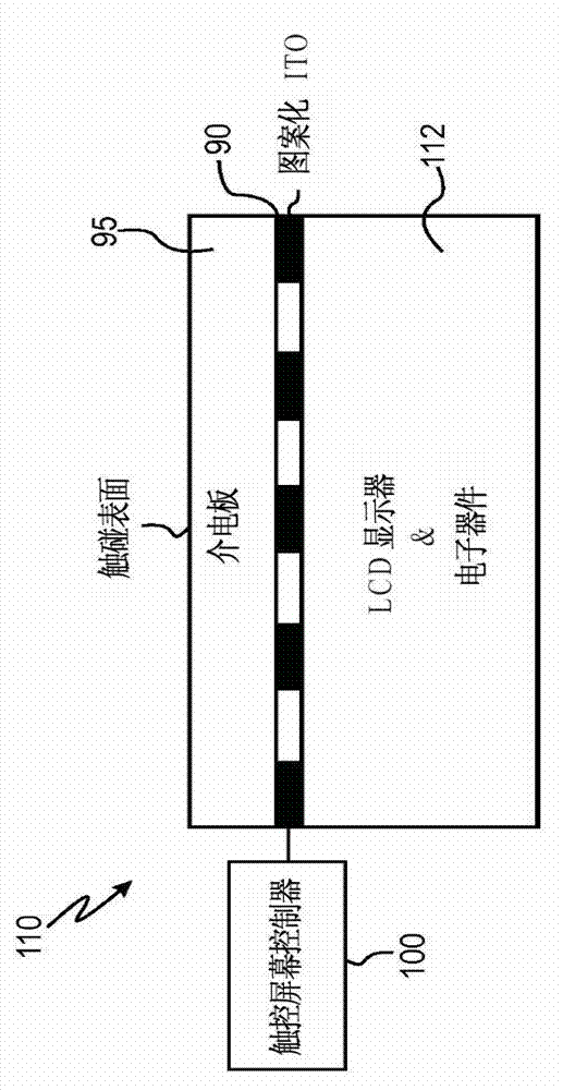
[0041] Such as figure 1 As shown, a capacitive touch screen system 110 usually consists of the following: a lower layer of LCD (or OLED) display 112, an upper layer of touch screen (or touch sensing panel or) 90, a set on the touch screen Dielectric plate (or protective cover) 95 above 90 , and a touch screen controller (or microprocessor, application specific integrated circuit (ASIC) or central processing unit (CPU)) 100 . It should be noted that besides the LCD display or the OLED display below the touch screen 90 , other image displays may also be provided.

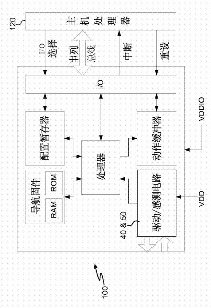
[0042] figure 2 A block diagram of one embodiment of a touch screen controller 100 is shown. In one embodiment, the touch screen controller 100 may be an Avago Technologies® modified according to the teachings herein TMARMI-5000 ASIC or chip 100. In one embodiment, the touch screen controller is a low power capacitive touch panel controller designed to provide a touch screen system with high precision screen navi...


PUM


Abstract

Disclosed are capacitive touch screen or touch panel systems, devices and methods which increase the dynamic range of touches that may be detected on a capacitive touch screen or touch panel. Increased dynamic range is provided by employing automatic gain control methodologies and circuitry to process signals corresponding to individual mutual capacitance cells in a touch screen or touch panel. The effective gain of each individual cell of a touch panel sensor can be equalized without causing deterioration in the sensor's ability to track touches of interest.

Description

technical field [0001] Various embodiments described herein are in the field of touchscreen or touchpad systems, devices, components and methods for using capacitive sensing technology to detect touches on a touch screen or touch panel. Background technique [0002] Capacitive touch panel sensors include touch screens or touch panels that include an array of sensing cells. A touch causes the capacitance of one or more cells below the touched area to change. The touch screen controller detects and locates the capacitance changes by analyzing the signals generated by the units due to the capacitance changes. These signals are analog amplified and filtered, then digitized and then digital signal processed. The main result of this analysis is to determine the affected cell locations and thus the corresponding touch locations. [0003] However, the capacitance values ​​of the cells in any given array may vary widely. Due to changes in nature, changes in the characteristics o...

Claims


Application Information

Patent Timeline
IPC IPC(8): G06F3/044H03G3/20
CPCH03G3/20H03G3/3089H03G3/002G06F3/044G06F3/0416G06F3/04166
Inventor 凱尼斯·魁戴尔麦可·布朗斯南杰瑞菲·史顿汤玛士·墨菲
Owner PIXART IMAGING INC
Learn More