
Control method of wind power generation double-feed converter space vector pulse width modulation (SVPWM) based on variable switching frequency
A doubly-fed converter, switching frequency technology, applied in the direction of output power conversion devices, electrical components, etc., can solve the problems of high temperature rise of switching devices, affecting system efficiency, large current, etc., to improve output efficiency, optimize Control strategy, effect of balancing switching losses
Patent Information
- Authority / Receiving Office
- CN · China
- Current Assignee / Owner
- Publication Date
- 2012-11-21
- Estimated Expiration
- Not applicable · inactive patent
Smart Images
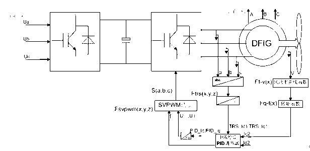
Figure 1 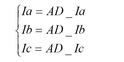
Figure 2 
Figure 3
Abstract
Description
technical field
[0001] The invention relates to wind power generator drive technology, in particular to a control strategy of a variable switching frequency wind power double-fed converter SVPWM, which belongs to the field of power electronics and electric drive. Background technique
[0002] In the application of doubly-fed wind power converters, the grid-side and machine-side dual SVPWM control technology is generally used. The double SVPWM converter has good input and output characteristics, and the power can flow in both directions, so that both the grid side and the machine side can absorb or emit energy; use the voltage vector orientation to calculate the decomposed d and q axis components, so as to control them separately . Among them, in the previous SVPWM modulation, the switching frequency is a fixed constant. In the case of high wind speed, the power fed into the power grid by the doubly-fed wind turbine is relatively high, and the current is large. At this time,...
Examples
Embodiment Construction
[0010] Below in conjunction with accompanying drawing and specific embodiment, the present invention is described in detail as follows.
[0011] Implementation link one: if figure 1 As shown, in the case of normal grid-connected power generation of the double-fed motor, the three-phase current on the rotor side of the motor is sampled, and the voltage value of the three-phase stationary coordinate system is converted to the two-phase synchronous rotating coordinate system. The specific calculation function is as follows:
[0012] Ia = AD _ Ia Ib = AD _ Ib Ic = AD _ Ic (Formula 1)
[0013] TRS_Id 1 / TRS_Iq 1 =Ft...