Signal transceiver

A signal transceiver and signal transmission technology, which is applied in amplifiers, power amplifiers, gated amplifiers, etc., can solve problems such as difficulty

Active Publication Date: 2012-11-21
MEDIATEK INC
View PDF4 Cites 13 Cited by
  • Summary
  • Abstract
  • Description
  • Claims
  • Application Information

AI Technical Summary

Problems solved by technology

In a wireless communication system, since the receiver and the transmitter are relatively complex circuits, it is necessary to enable the external transmitter/receiver swit...

Method used


Image

  • Signal transceiver
  • Signal transceiver
  • Signal transceiver

Examples


Embodiment Construction

[0016] Certain terms are used throughout the description to refer to particular elements. Those skilled in the art should understand that hardware manufacturers may use different terms to refer to the same component. In this specification, the difference in names is not used as a way to distinguish components, but the difference in function of components is used as a criterion for distinguishing. "Includes" mentioned throughout the specification is an open-ended term, so it should be interpreted as "including but not limited to". In addition, the term "coupled" here includes any direct and indirect means of electrical connection. Therefore, if it is described in the text that a first device is coupled to a second device, it means that the first device can be directly electrically connected to the second device. second device, or indirectly electrically connected to the second device through other devices or connection means.

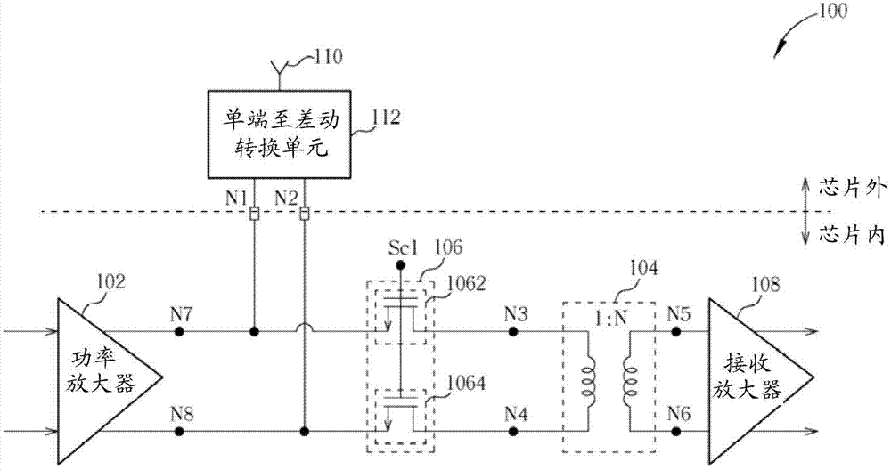
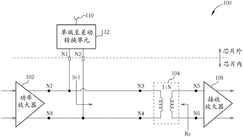
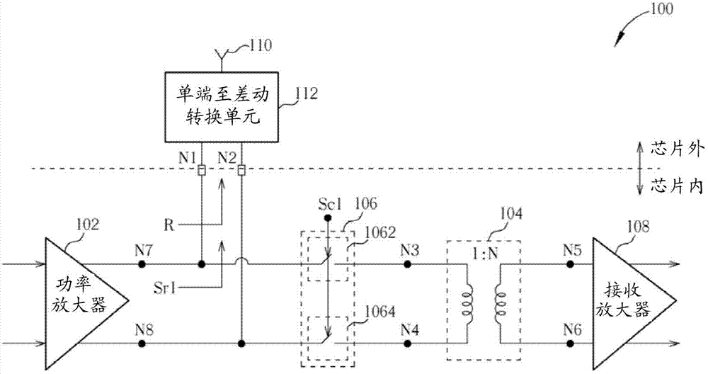
[0017] Please refer to Figure 1, figure 1 It is...


PUM


Abstract

The invention provides a signal transceiver. The signal transceiver includes a first power amplifier coupled to a chip output port of a chip; an impedance transforming circuit; a switching circuit arranged to selectively couple the chip output port to a first port of the impedance transforming circuit; and a receiving amplifier coupled to a second port of the impedance transforming circuit. The signal transceiver can improve linearity of a power amplifier in the chip and reduce the noise index of a low noise amplifier in the chip.

Description

technical field [0001] The present invention relates to a signal transceiver, in particular to a signal transceiver with high linearity and low noise figure. Background technique [0002] A wireless communication system includes a receiver and a transmitter. When the wireless communication system operates in a Time-Division Duplex (TDD) mode, an external transmitter / receiver switch (Transmitter / Receiver switch, T / R switch) is connected between the transmitter and the Switching between receivers because both the transmitter and the receiver utilize the same antenna. Furthermore, when the wireless communication system is in operation, the external transmitter / receiver switch selectively couples the antenna to the transmitter or the receiver. In addition, in a conventional wireless communication system, the external transmitter / receiver switch is usually coupled in series with the receiver instead of the transceiver. In the receive mode, when the external transmitter / receive...

Claims


Application Information

Patent Timeline
IPC IPC(8): H04B1/40
CPCH03F3/24H03F1/56H03F2203/7221H03F2200/387H03F2203/7209H03F2200/429H03F2200/06H03F3/45475H03F2203/45616H03F3/72H03F2200/541H03F2203/7236
Inventor 简敦正吴家欣陈宗明李翼安
Owner MEDIATEK INC
Why Eureka
Try Eureka