Plasma display panel

A display panel, plasma technology, applied in the direction of alternating current plasma display panels, discharge tubes, electrical components, etc., can solve the problems of increasing the applied voltage, increasing the charge decay rate, reducing the discharge delay and poor lighting, etc.

Inactive Publication Date: 2012-11-21
PANASONIC CORP
View PDF8 Cites 0 Cited by
  • Summary
  • Abstract
  • Description
  • Claims
  • Application Information

AI Technical Summary

Problems solved by technology

However, countermeasures are required as follows: In the case of improving the electron emission characteristics by mixing impurities into the protective layer, when it is intended to accumulate charges on the surface of the protective layer and use it as a memory function, the attenuation due to the decrease of charges with the passage of time rate becomes large, it is necessary to increase the applied voltage to suppress this
[0014] On the other hand, in the example of forming magnesium oxide (MgO) crystal particles on the magnesium oxide (MgO) protective layer, although the discharge delay can be reduced and the lighting failure can be reduced, there is a problem that the discharge voltage cannot be lowered.

Method used


Image

  • Plasma display panel
  • Plasma display panel
  • Plasma display panel

Examples


Embodiment approach 1

[0035] Hereinafter, the PDP in Embodiment 1 will be described.

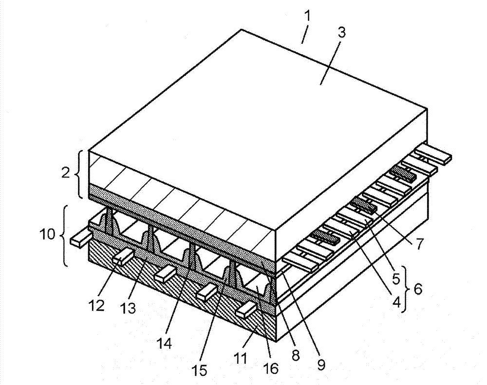
[0036] figure 1 It is a perspective view showing the structure of the PDP in one embodiment. The basic structure of the PDP 1 is the same as that of a general AC surface discharge type PDP. Such as figure 1 As shown, in PDP 1, a front panel 2 composed of a front glass substrate 3 and the like and a rear panel 10 composed of a rear glass substrate 11 and the like are arranged to face each other, and the outer periphery thereof is hermetically sealed with a sealing material composed of glass frit or the like. . In the discharge space 16 inside the sealed PDP1, at 400Torr~600Torr (5.3×10 4 pa~8.0×10 4 Pa) pressure discharge gas such as xenon (Xe) and neon (Ne) is sealed.

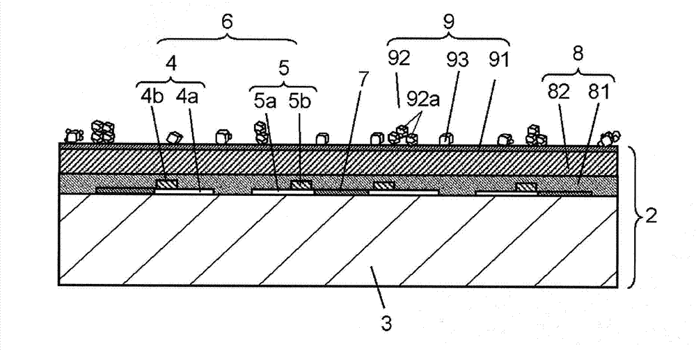
[0037] On front glass substrate 3 of front panel 2 , a pair of strip-shaped display electrodes 6 and black stripes (light shielding layers) 7 composed of scan electrodes 4 and sustain electrodes 5 are arranged in parallel to each other. On ...

Embodiment approach 2


PUM

PropertyMeasurementUnit
particle diameteraaaaaaaaaa
cover factoraaaaaaaaaa

Abstract

A plasma display panel, wherein aggregate particles (92) that are an aggregate of a plurality of magnesium oxide crystal particles (92a), and metal oxide particles (93) are dispersed across an entire surface of an under-layer (91) of a protective layer (9). The metal oxide particles (93) include at least two metal oxides selected from a group composed of magnesium oxide, calcium oxide, strontium oxide and barium oxide. Of the two metal oxides included in the metal oxide particles (93), an X-ray diffraction analysis diffraction angle peak at a specific orientation of the metal oxide particles (93) is between an X-ray diffraction analysis diffraction angle peak at a specific orientation of one metal oxide and an X-ray diffraction analysis diffraction angle peak at a specific orientation of the other metal oxide.

Description

technical field [0001] The present invention relates to a plasma display panel used in display devices and the like. Background technique [0002] Since plasma display panels (hereinafter referred to as PDPs) can achieve high definition and large screens, 100-inch-class televisions and the like have already been commercialized. In recent years, as the application of PDPs to high-definition TVs with twice or more scanning lines compared with the conventional NTSC system has progressed, in order to cope with energy issues, efforts have been made to further reduce power consumption, and environmental issues have been considered. The requirements for PDPs that do not contain lead components are also increasing. [0003] A PDP basically consists of a front panel and a rear panel. The front panel is composed of: a glass substrate of sodium borosilicate glass manufactured by a float glass process; and a stripe-shaped transparent electrode and a bus electrode formed on one main su...

Claims


Application Information

Patent Timeline
Patent Type & Authority Applications(China)
IPC IPC(8): H01J11/40H01J11/12
CPCH01J11/40H01J11/12
Inventor 辻田卓司三浦正范后藤真志
Owner PANASONIC CORP
Why Eureka
Try Eureka