Large-span railway desk type concrete arch bridge structure

A large-span, concrete technology, applied in the field of bridge construction, can solve the problems of poor coordination between the upper structure of the arch and the main arch ring, many columns on the arch, and limited lateral stiffness, so as to reduce the construction difficulty and construction risk, reduce the project cost, Reasonable effect of structural stress

Inactive Publication Date: 2012-11-28
CHINA RAILWAY ERYUAN ENG GRP CO LTD
View PDF5 Cites 20 Cited by
  • Summary
  • Abstract
  • Description
  • Claims
  • Application Information

AI Technical Summary

Problems solved by technology

The bridge deck of railway bridges is often narrow, the width of the main arch ring needs to be coordinated with it, and the lateral stiffness is limited to a certain extent. Although it can still meet the requirements of lateral stiffness of small-span railway bridges, it is difficult to meet the requirements of lateral stiffness of large-span railway bridges
In order to improve the lateral stiffness of long-span railway bridges and ensure the safety of trains and the comfort of passengers under operating conditions, it is necessary to increase the width of the arch ring, such as the overall widening of the arch ring. Poor coordination, which affects the bridge landscape effect; and increases the amount of masonry for the main arch, resulting in waste of materials
As for the arch structure, the arch structures of the upwardly supported concrete arch bridges in my country all adopt a simply supported structure system. Due to the limited spanning capacity of the simply supported beams, as the span of the arch bridge increases, the columns on the arch are higher, especially near the arch foot. 1# pier column (for example, the span is 500m arch bridge, the rise-span ratio is 1 / 5, and the 1# column on the arch is close to 100m), the longitudinal stiffness of the arch pier column is difficult to meet the design requirements, and there are many columns on the arch, which increases the construction Difficulty and construction risk

Method used


Image

  • Large-span railway desk type concrete arch bridge structure
  • Large-span railway desk type concrete arch bridge structure
  • Large-span railway desk type concrete arch bridge structure

Examples


Embodiment Construction

[0018] The present invention will be further described below in conjunction with drawings and embodiments.

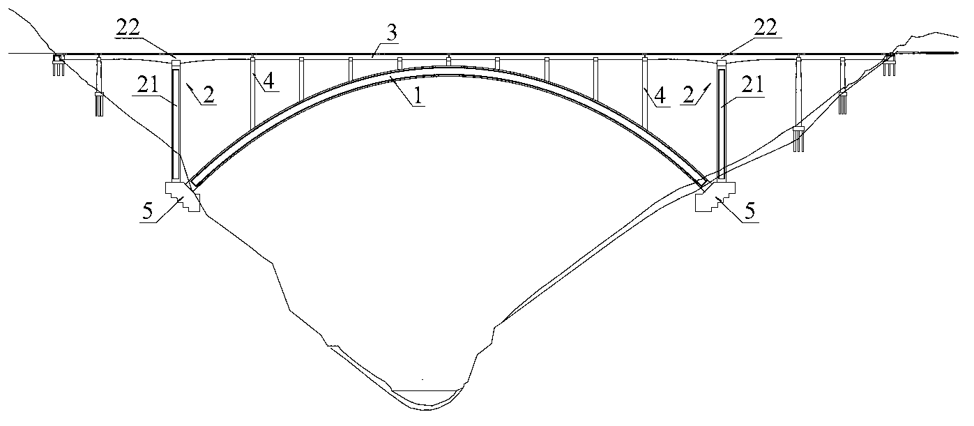
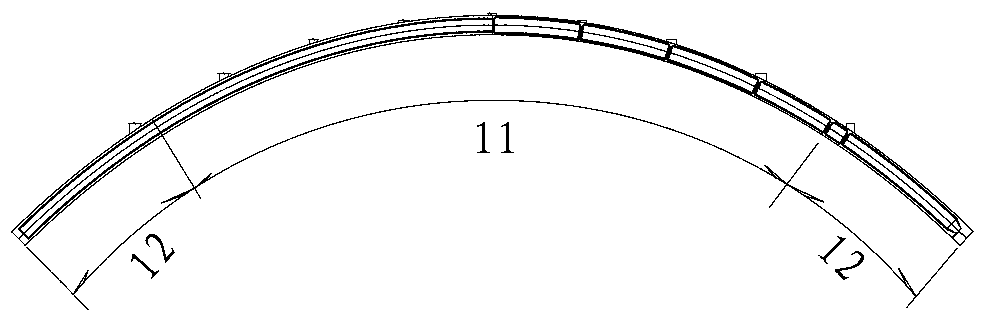
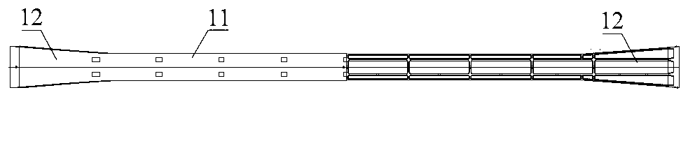
[0019] refer to figure 1 , the structure of the large-span railway overhead concrete arch bridge of the present invention includes a main arch ring 1, a junction pier 21, an arch upper beam 3, an arch upper column 4 and an abutment foundation 5, and the junction piers 21 and the arches on both sides of the main arch ring 1 The feet are supported on the abutment foundation 5, and the arch beam 3 is supported on the main arch ring 1 through the arch column 4. refer to Figure 1 to Figure 4 , the main arch ring 1 is a single-box multi-chamber cross-section box-shaped plate arch of equal height. , increasing the lateral stiffness of the main arch ring, thus forming a new type of top-supporting box-shaped plate arch shape.

[0020] Figure 4 with Figure 5 A typical structure of the main arch 1 is shown, that is, the main arch 1 is a single-box three-chamber cross-secti...


PUM


Abstract

The invention provides a large-span railway desk type concrete arch bridge structure. When transverse and longitudinal rigidities and stresses of the arch bridge structure are preferably satisfied, construction difficulties and construction risks of a main arch ring and an arch structure can be reduced, and engineering cost is greatly reduced. The large-span railway desk type concrete arch bridge structure comprises the main arch ring (1), a border pier (21), an arch beam (3), an arch column (4) and an arch support foundation (5), wherein arch feet on two sides of the border pier (21) and the main arch ring (1) are supported on the arch support foundation (5); the arch beam (3) is supported on the main arch ring (1) by the arch column (4). The main arch ring (1) is equal-height single-box and multi-chamber section box-like plate arch; the arch top of the main arch ring is an equal-width section (11); and arc foot parts close to two sides of the main arch ring are linear widened sections (12). The border pier (21) forms a border pier T structure (2) together with a T structure beam (22) fixedly connected with the top end of the border pier (21); and the arch beam (3) is a multi-span continuous beam.

Description

technical field [0001] The invention relates to a bridge structure, in particular to a large-span railway top-supporting concrete arch bridge structure for a passenger-dedicated railway crossing a "V"-shaped canyon terrain in a mountainous area. Background technique [0002] Passenger-dedicated railway bridges have high rigidity requirements. Among the various types of bridges, cable-stayed bridges and suspension bridges are difficult to improve their own rigidity and have large temperature deformation, so it is difficult to meet the relevant requirements of high-speed train operation. As a commonly used bridge type, the arch bridge not only has a large spanning capacity and overall rigidity, but also can be well combined with the canyon terrain. Concrete arch bridges, in particular, have many advantages, such as high rigidity, strong bearing capacity, little influence by temperature changes, low construction cost, and small post-maintenance and repair workload. According t...

Claims


Application Information

Patent Timeline
Patent Type & Authority Applications(China)
IPC IPC(8): E01D4/00
Inventor 徐勇陈列何庭国陈克坚谢海清胡京涛游励晖任伟黄毅胡玉珠杨国静韩国庆
Owner CHINA RAILWAY ERYUAN ENG GRP CO LTD
Why Eureka
Try Eureka