Three-dimensional simulation device for edge/bottom water reservoir

A technology of edge-bottom water reservoirs and simulation devices, applied in the field of experimental devices for the study of multiphase fluid flow laws, can solve the problem of not considering the observation of bottom water ridge advance laws, oil field similarities, and fluid movement laws And other issues

Active Publication Date: 2012-11-28
CHINA UNIV OF PETROLEUM (BEIJING) +1
View PDF8 Cites 26 Cited by
  • Summary
  • Abstract
  • Description
  • Claims
  • Application Information

AI Technical Summary

Problems solved by technology

[0002] The three-dimensional reservoir physical simulation technology can reflect the movement of underground fluid more realistically and is widely used in the petroleum industry. At present, there are many physical simulation experiments for the development of bottom water reservoirs at home and abroad, but the existing two-dimensional experimental equipment does not take into account Similarity to the oil field; the existing 3D experimental device does not take into account the observation of the law of bottom water ridge advance, and cannot measure the law of fluid movement inside the experimental device

Method used


Image

  • Three-dimensional simulation device for edge/bottom water reservoir
  • Three-dimensional simulation device for edge/bottom water reservoir
  • Three-dimensional simulation device for edge/bottom water reservoir

Examples


Embodiment 1

[0030] When this physical simulation device is used for bottom water reservoir exploitation experiment.

[0031] Such as Figure 4 As shown, in this embodiment, the water injection hole 8 on the bottom surface of the main body is sequentially connected to an on-off valve 17, a liquid flow meter 18 and a first displacement pump 16 by a pipe body.

[0032] A simulated wellbore 21 is connected to a functional measurement point 4 on the gland, and is sequentially connected to an on-off valve 17, an intermediate container 19 and a second displacement pump 23 by a pipe body.

[0033] A pressure measuring device 13 is connected to a functional measuring point 4 on the side wall; a saturation measuring device 14 is connected to another functional measuring point 4 on the side wall; the pressure measuring device 13 and the saturation measuring device 14 are connected to a computer 15Connect.

[0034] The bleed hole 7 is connected to a bleed pipeline through a switch valve 17.

[0035] Such as ...

Embodiment 2

[0047] In this embodiment, the physical simulation device is used to perform an experimental simulation of edge water reservoir production.

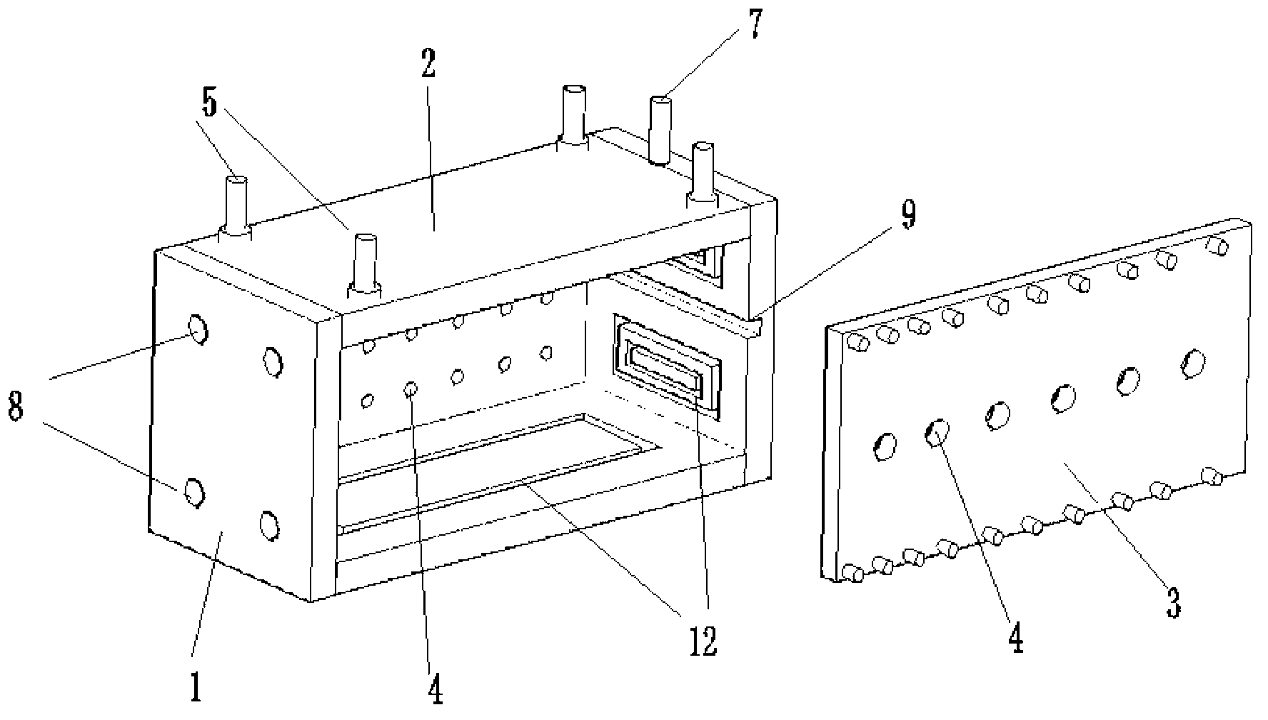
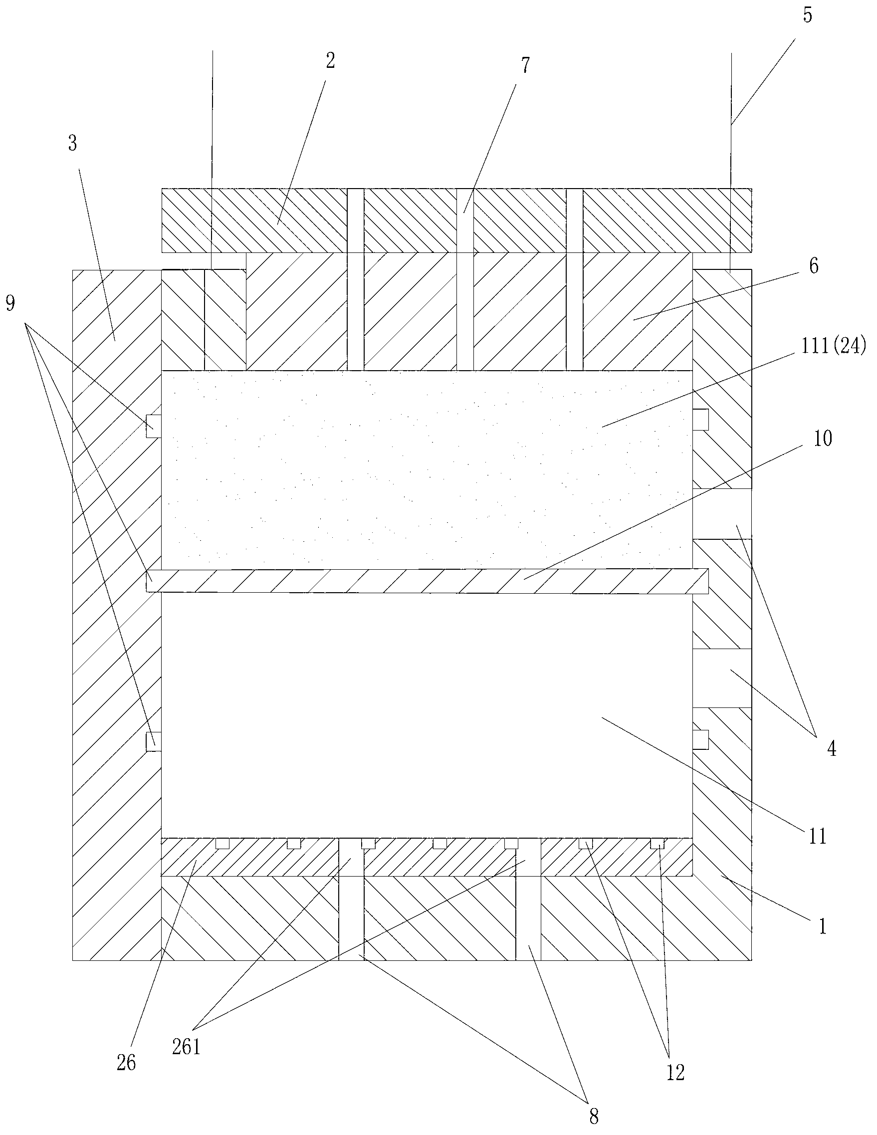
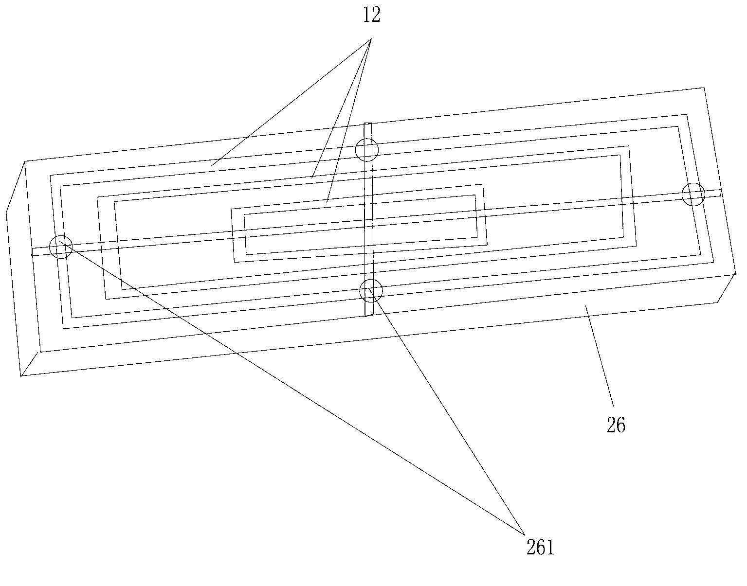
[0048] The structure and principle of this embodiment and embodiment 1 are basically the same, the difference lies in that, as figure 2 As shown, in this embodiment, in the ring groove 9 provided on the side wall around the main body, a partition 10 is sealed and embedded, and the partition 10 separates the accommodating cavity 11 into upper and lower sealed spaces (to make The thickness of the accommodating cavity is variable). Such as Image 6 , Figure 7 As shown, in this embodiment, the on-off valve 17, a liquid flow meter 18, and a first displacement pump 16 are sequentially connected to the water injection hole 8 on the side wall of the body by a pipe body, and the water injection hole 8 is located Above the ring groove 9.

[0049] The specific use process of the physical simulation device used in the edge water reservoir of the prese...


PUM


Abstract

The invention relates to a three-dimensional simulation device for an edge/bottom water reservoir. The device comprises a body and a detachable moving side wall which is arranged on the side surface of the body, wherein an accommodating cavity is formed in the body; a gland is arranged on the top of the body; a piston is arranged on the lower part of the gland; a plurality of vent holes communicated with the accommodating cavity are formed in the gland; an annular groove in which a clapboard can be arranged in a sealing mode is formed in the peripheral side wall of the accommodating cavity; a plurality of poroid functional measuring points are formed on all the wall surfaces of the body and the gland and are communicated with the accommodating cavity in a controlled mode; a plurality of granular porous media are fully filled in the accommodating cavity; and a plurality of pipe columns for simulating a mineshaft are arranged in the granular porous media in the accommodating cavity. By the device, edge/bottom water reservoirs which have different thicknesses and are developed at different dip angles in different displacement modes and different well pattern types can be subjected to physical simulation experiment, so that an oil-water percolation mechanism of an oil and gas reservoir can be researched, and the effects of the edge/bottom water reservoirs in different development modes can be evaluated.

Description

Technical field [0001] The invention relates to an experimental device for the study of multiphase fluid flow laws, in particular to a three-dimensional simulation device for simulating different stratum dip, different water body types, and multi-well type joint development of edge-bottom water reservoirs. Background technique [0002] Three-dimensional reservoir physical simulation technology can truly reflect the laws of underground fluid movement and is widely used in the petroleum industry. At present, there are many physical simulation experiments aimed at the development of bottom water reservoirs at home and abroad, but the existing two-dimensional experimental devices have not considered Similarity with the oil field; the existing three-dimensional experimental device does not take into account the observation of the law of the bottom water ridge, and cannot measure the law of fluid movement inside the experimental device. [0003] As a result, the inventor, based on years ...

Claims


Application Information

Patent Timeline
Patent Type & Authority Applications(China)
IPC IPC(8): E21B49/00E21B47/00E21B47/10E21B47/06
Inventor 程林松赵伦刘佳范子菲
Owner CHINA UNIV OF PETROLEUM (BEIJING)
Why Eureka
Try Eureka