Surface luminous body realizing method with patterning function and device for realizing patterned luminescence

A surface luminous body and a technology of a realization method, applied in the field of optics, can solve problems such as waste of energy, environmental pollution, and only overall plane light emission, and achieve the effects of energy saving, low cost, and convenient graphic design changes

Inactive Publication Date: 2012-11-28
郴州市丰霖光电有限公司
View PDF8 Cites 20 Cited by
  • Summary
  • Abstract
  • Description
  • Claims
  • Application Information

AI Technical Summary

Problems solved by technology

[0004]The purpose of the present invention is to overcome the technical problems of waste of energy in injection molding, environmental pollution caused by printing, and only overall plane light emission in the traditional technology, and provide an energy-saving , A method for realizing a patterned surface illuminant that protects the environment and can emit light locally, and a device for realizing patterned light

Method used


Image

  • Surface luminous body realizing method with patterning function and device for realizing patterned luminescence
  • Surface luminous body realizing method with patterning function and device for realizing patterned luminescence
  • Surface luminous body realizing method with patterning function and device for realizing patterned luminescence

Examples


Embodiment

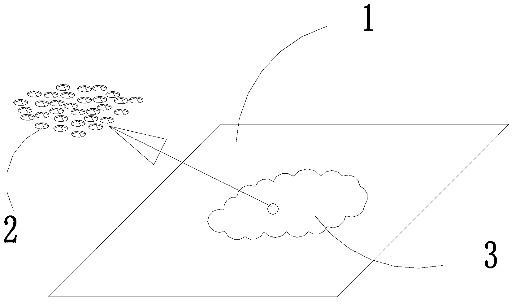
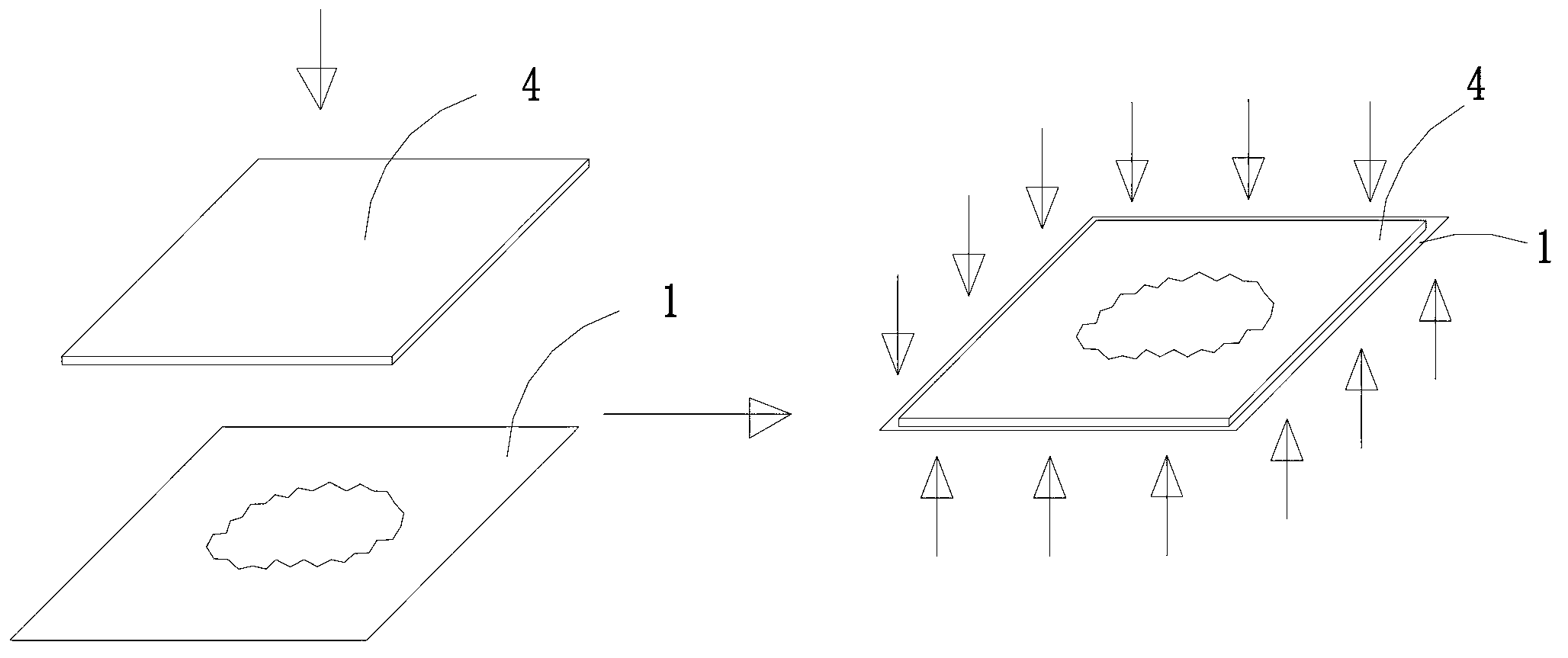
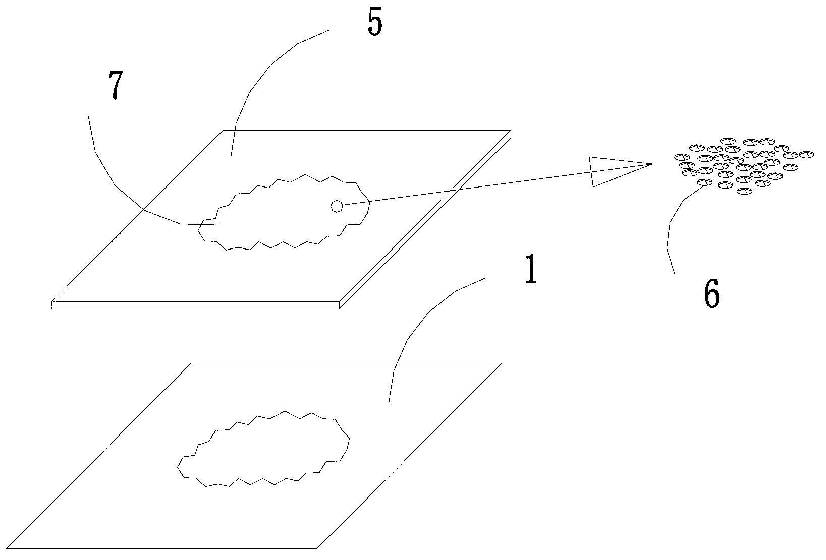
[0038] combine Figure 1 to Figure 3 As shown, a method for implementing a surface illuminant with graphics,

[0039] Step 1: making a metal mold core plate 1, with micro-optical elements 2 on the metal mold core plate 1, and the micro-optical elements 2 are arranged and assembled on the metal mold core plate 1 according to predetermined requirements to form a graphic outline 3;

[0040] The above-mentioned metal core plate 1 is obtained by the invention patent of 201210217175.9 filed by the same applicant on June 26, 2012. Graphical micro-structured optical elements are collectively produced on a metal mold core. In this embodiment, the optical elements on the metal mold core are transferred to the light-transmitting light guide by means of pressurization and heating. It is characterized by light guide Arbitrary luminescence patterns including overall planar luminescence can be realized quickly and at low cost on the body.

[0041] The prior patent mentioned in this embodim...


PUM

PropertyMeasurementUnit
thicknessaaaaaaaaaa
thicknessaaaaaaaaaa

Abstract

The invention discloses a surface luminous body realizing method with a patterning function and a device for realizing patterned luminescence. The method comprises the following steps of: manufacturing a metal die core plate which is provided with a micro optical element; putting a transparent plastic plate onto the metal die core plate; applying a pre-determined pressure and a pre-determined temperature to the surface of the plastic plate from top to bottom and to the metal die core plate from bottom to top respectively; separating the metal die core plate from the plastic plate, and transcribing a pattern profile on the metal die core plate onto the transparent plastic plate to form a non-light tight light conductor with a patterned optical element; transcribing the micro optical element on the metal die core plate onto the non-light tight light conductor to form a transparent optical element structure; and injecting light energy into the non-light tight light conductor, transmitting light rays out of the non-light tight light conductor at a position where the optical element structure is positioned, and forming a visible luminous pattern on the non-light tight light conductor.

Description

technical field [0001] The invention relates to the field of optical technology, in particular to a method for realizing a patterned surface illuminant and a device for realizing patterned light emission. Background technique [0002] Liquid crystal display backlight modules and flat panel lighting modules are currently the main thin light-emitting structures, and their light guides are realized by injection molding or by cutting and processing dots. Since the purpose of these modules is to provide as large a The light-emitting surface, so except for the edge width of the module, almost the entire inner plane is emitting light, which cannot show a graphical light-emitting pattern. Injection mold development costs are high and the processing cycle is long, while the ink dots on the printed light guide plate are large in size, which are easily observed by the naked eye and affect the visual effect. Methods such as dot injection molding or cutting and processing dots have low ...

Claims


Application Information

Patent Timeline
Patent Type & Authority Applications(China)
IPC IPC(8): F21S8/00F21V8/00F21V5/00
Inventor 田耕何志能
Owner 郴州市丰霖光电有限公司
Why Eureka
Try Eureka