Reflective sheet and backlight unit

A technology for a backlight unit and a reflective sheet, applied in the field of reflective sheets, can solve the problems of uneven brightness, scratches on the light guide plate, bending of the reflective sheet, etc., and achieve the effect of high reflectivity and improved reflectivity

Inactive Publication Date: 2012-11-28
KEIWA INCORPORATED
View PDF6 Cites 5 Cited by
  • Summary
  • Abstract
  • Description
  • Claims
  • Application Information

AI Technical Summary

Problems solved by technology

[0008] However, even with the reflective sheet having the above-mentioned damage prevention layer, there is still a problem that scratches are generated on the light guide plate by the beads due to differences in the type and shape of the beads.
[0009] In addition, since the temperature of the reflective sheet is higher near the light source of the backlight unit, the above-mentioned conventional reflective sheet is warped due to the temperature, and there is a problem that brightness unevenness occurs due to the warp.

Method used


Image

  • Reflective sheet and backlight unit
  • Reflective sheet and backlight unit

Examples


Embodiment approach

[0073] The above-mentioned embodiment has the above-mentioned advantages due to the above-mentioned structure, but the present invention is not limited to the structure of the above-mentioned embodiment, and the design can be appropriately changed within the scope of the purpose of the present invention.

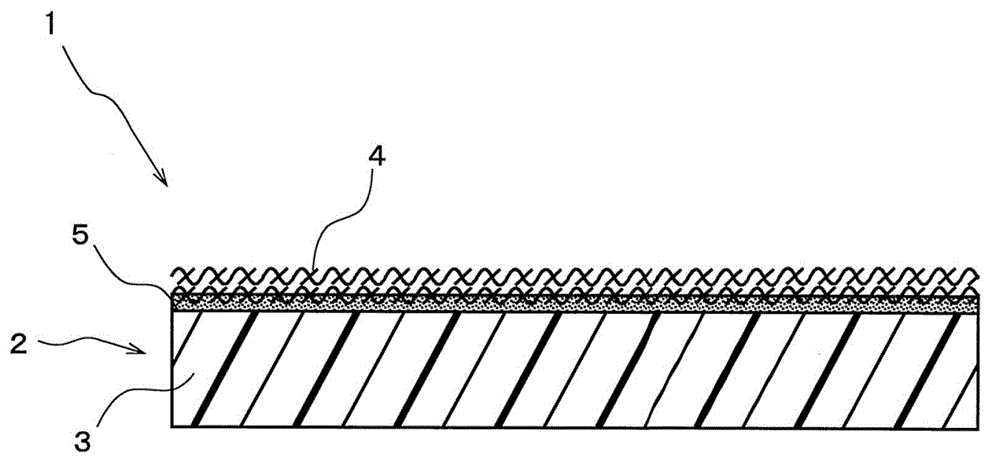
[0074] That is, in the above-mentioned embodiment, any one of the fiber gathering layer 4, the adhesive layer 5, and the sheet main body 2 has been described as being white, but the present invention is not limited thereto, as long as the desired reflectivity can be obtained. The design can be changed appropriately. Specifically, even if the fibers of the fiber accumulation layer 4 are colorless and transparent, and the white pigment is dispersed and contained in the adhesive layer 5, the reflective sheet 1 is within the scope of the object of the present invention. By dispersing and containing the white pigment in the adhesive layer 5 in this way, sufficient reflectivity ca...

Embodiment 1

[0081] A sheet made of white PET (polyethylene terephthalate) ("Lumira-E60L" manufactured by Toray Co., Ltd.) was used for the sheet main body (substrate sheet layer). The reflective sheet of Example 1 was fabricated by laminating and bonding a nonwoven fabric ("Taibeck" manufactured by DuPont) on the surface of the sheet main body by dry lamination. Here, as the adhesive for bonding the nonwoven fabric, a dry lamination adhesive ("E263" manufactured by Dainichi Seika Co., Ltd.) was mixed with 90% by mass of titanium oxide. The stacking amount of the mixture layer (converted into solid content) is 10g / m 2 .

Embodiment 2

[0083] The reflective sheet of Example 2 was obtained by the same method as in Example 1 except that no titanium oxide was mixed with the adhesive for dry lamination.


PUM


Abstract

The invention aims to provide a reflectie sheet and a backlight unit. The reflective sheet can prevent the overlapped surfaces such as the back surface of a light guide plate from being damaged and bonded and is free of the bending because of the heat from a light source. The backlight unit using the reflective sheet can realize the improvement and the uniformity of the brightness. The reflectie sheet applied on the backlight unit for reducing light loss is characterised by including a sheet main body which is sheet-shaped; and a fiber aggregation layer which is configured on one side of the surface of the sheet main body and is provided with a pluraltiy of fibers and gaps between the fibers. The back surface of the light guide plate is provided with the backlight unit with the reflective sheet, because the reflective sheet abutts against the light guide plate via the fiber aggregation layer, the damage on the back surface of the light guide plate can be prevented.

Description

technical field [0001] The present invention relates to a reflection sheet for a backlight unit that reduces light loss (diffusion), and a backlight unit using the reflection sheet. Background technique [0002] Liquid crystal display devices of the backlight type in which the liquid crystal layer is illuminated from the back to emit light are widely used, and backlight units such as edge light type and direct type are equipped on the bottom side of the liquid crystal layer. like figure 2 As shown, the edge light type backlight unit 30 generally includes: a light source 31, which is composed of rod-shaped LEDs; a square plate-shaped light guide plate 33, whose ends are arranged along the light source 31; The optical sheet 32 ​​is stacked on the front side of the light guide plate 33 ; and the reflective sheet 36 is stacked on the back side of the light guide plate 33 . The optical sheets 32 respectively have specific optical properties such as refraction and diffusion. Spe...

Claims


Application Information

Patent Timeline
IPC IPC(8): F21V7/22F21S8/00G02F1/13357
CPCG02B5/0883G02F1/133615
Inventor 辻孝弘
Owner KEIWA INCORPORATED
Why Eureka
Try Eureka