Spiral runner type sewage heat exchanger

A spiral flow channel and heat exchanger technology, applied in the direction of heat exchanger type, heat exchanger shell, indirect heat exchanger, etc., can solve the problems of increased sewage flow resistance, small flow resistance, easy fouling, etc., to achieve flow Smooth, small flow resistance, not easy to fouling effect

Inactive Publication Date: 2012-11-28
HIT HARBIN INST OF TECH KINT TECH
View PDF6 Cites 7 Cited by
  • Summary
  • Abstract
  • Description
  • Claims
  • Application Information

AI Technical Summary

Problems solved by technology

Every time the process is changed and the direction is changed, there will be a fierce impact of the flowing water on the wall of the device, which greatly increases the resistance of the sewage flow. At the same time, at the turning point of the flow, it is easy to accumulate scale and cause blockage.
So far, there is no such sewage heat exchanger: the sewage flows smoothly, without turning, without dead angle, small flow resistance, and not easy to accumulate scale

Method used


Image

  • Spiral runner type sewage heat exchanger
  • Spiral runner type sewage heat exchanger
  • Spiral runner type sewage heat exchanger

Examples


Embodiment Construction

[0024] The present invention will be described in further detail below in conjunction with the accompanying drawings and embodiments.

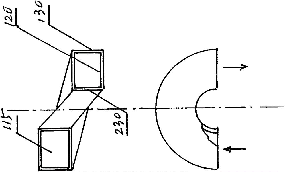
[0025] figure 1 The basic principle diagram of the embodiment of the spiral channel type sewage heat exchanger of the present invention is given.

[0026] The basic principle of the embodiment of the spiral channel type sewage heat exchanger of the present invention is as follows: figure 1 shown. The sewage pipe 115 is in a spiral shape, similar to a threaded cylindrical spiral. The sewage pipe 115 rotates along a fixed radius around a vertical central axis. While the sewage channel is rotating, it is still reducing the height. Every time the sewage channel turns around in the horizontal direction, it will drop a pitch in the vertical direction. The cross-section of the sewage pipe 115 is a rectangle, the upper and lower sides of this rectangle are partition walls 120 , one vertical side thereof is the inner wall 230 of the sewage flow ch...


PUM


Abstract

The invention provides a spiral runner type sewage heat exchanger. The sewage heat exchanger comprises a barrel, a sewage runner and a clear water runner. The sewage runner and the clear water runner are arranged in the barrel vertically at interval and have common dividing walls, and sewage and clear water exchange heat through the dividing walls. The sewage and the clear water conversely flow in the runners respectively, and trends of the sewage runner and the clear water runner in the barrel are double-head cylindrical spirals. The barrel is a shell of the spiral runner type sewage heat exchanger, is cylindrical, and is placed vertically. The sewage runner comprises a sewage inlet, a sewage pipeline and a sewage outlet; the cross section of the sewage pipe is rectangular and is encircled by an inner wall, the barrel and the upper and lower dividing walls; the swage enters from the sewage inlet on the top of the heat exchanger, and flows from top to bottom along the cylindrical spirals in the sewage pipeline; and the clear water enters from a clear water inlet at the bottom of the heat exchanger, and flows from top to bottom along the cylindrical spirals in a clear water pipeline. The sewage heat exchanger has the advantages of low flowing resistance, scaling prevention and good heat exchange effect.

Description

technical field [0001] The invention relates to heat exchange equipment, in particular to a spiral channel type sewage heat exchanger. Background technique [0002] Using urban sewage as a cold and heat source to heat and air-condition buildings can directly reduce the consumption of other scarce energy sources, and at the same time achieve the purpose of waste utilization. It is an important measure for resource regeneration, development of circular economy, construction of a conservation-minded society, and a friendly environment. . [0003] The sewage source heat pump relies on the physical state cycle of the refrigerant inside the heat pump unit. In winter, heat is absorbed from the sewage and heated by the heat pump unit to heat the building. In summer, the heat in the building is transferred to the sewage through the heat pump unit to achieve cooling. Sewage replaces the cooling tower, which has the outstanding advantages of high efficiency, energy saving, environment...

Claims


Application Information

Patent Timeline
Patent Type & Authority Applications(China)
IPC IPC(8): F28D7/02F28F9/00F28F19/00F28F21/08
Inventor 李金峰李伟尚德敏李玉祥
Owner HIT HARBIN INST OF TECH KINT TECH
Why Eureka
Try Eureka