Narrow-band antenna test method based on return loss compensation

A return loss, narrowband antenna technology, applied in the direction of the antenna radiation pattern, can solve problems such as inability to remove interference, and achieve the effects of improving distance resolution, low reflected power, and high radiation efficiency

Inactive Publication Date: 2012-11-28
NORTHWESTERN POLYTECHNICAL UNIV
View PDF6 Cites 9 Cited by
  • Summary
  • Abstract
  • Description
  • Claims
  • Application Information

AI Technical Summary

Problems solved by technology

For antennas whose operating bandwidth is less than 30MHz, the distance resolution

Method used


Image

  • Narrow-band antenna test method based on return loss compensation
  • Narrow-band antenna test method based on return loss compensation
  • Narrow-band antenna test method based on return loss compensation

Examples


Embodiment Construction

[0035] Now in conjunction with implementation steps, accompanying drawing, the present invention is described as a further example:

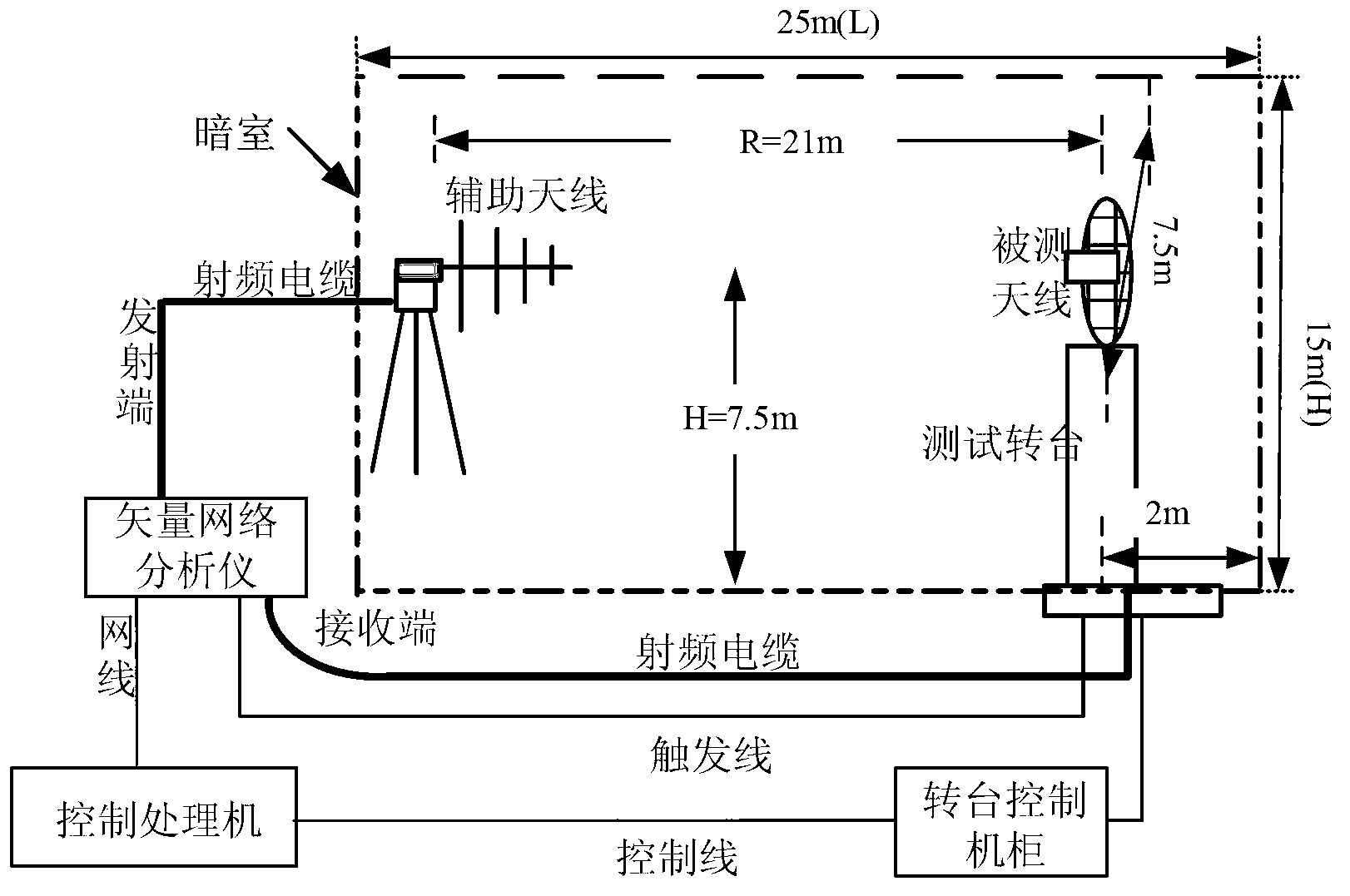
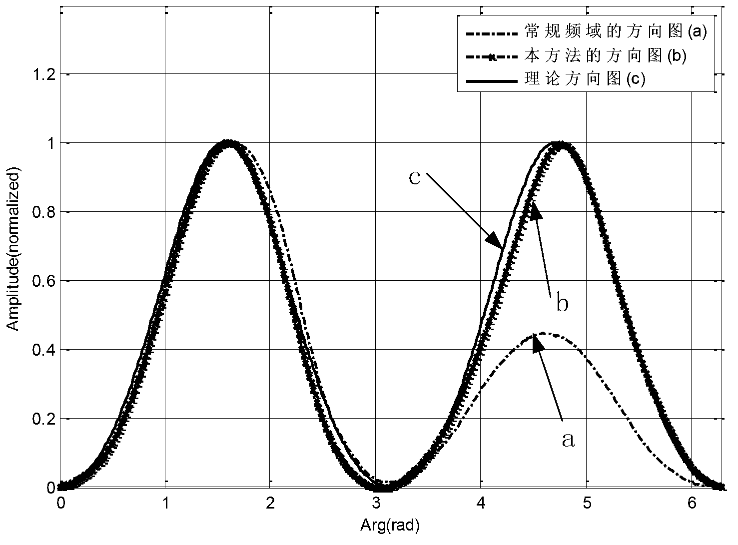
[0036] Select a half-wave vibrator antenna under test with a working frequency of 300MHz, and install it in a microwave anechoic chamber with a size of 25(L)×15(W)×15(H)(m) for testing. The structure diagram of the test system Such as figure 2 As shown, the auxiliary antenna is UPA6109. Antenna pattern with a test frequency of 300MHz.

[0037] According to the present invention, its implementation process is as follows:

[0038] 1) Build an antenna test system: the auxiliary antenna at the transmitting end and the antenna under test at the test end are at the same height and on the same axis;

[0039] 2) Combined with the structure diagram of the test system and the size of the example darkroom, the minimum wave path distance is the distance from the signal emitted by the transmitting antenna vertically irradiated to the front wall and refle...


PUM


Abstract

The invention relates to a narrow-band antenna test method based on return loss compensation. The narrow-band antenna test method is characterized by comprising the following steps of: constructing an antenna test system, wherein an auxiliary antenna at a transmitting end and a tested antenna at a test end are positioned at the same height and on the same axial line; and according to a reflection coefficient of a certain frequency point, calculating radiation energy loss of a frequency point corresponding to the antenna, and performing value compensation, so that a time domain waveform is free of distortion after time-frequency conversion is performed. By the narrow-band antenna test method, a test bandwidth is expanded, so that an ideal time domain resolution is obtained, and the influence of multipath interference can be effectively suppressed, a test technology is applied to antenna test at a low frequency band (less than 300 MHz) in a microwave anechoic chamber and open area test with a near-end strong reflector, and therefore, the precision of a direction graph of a low-frequency and narrow-band antenna is improved by 2 dB or so, and a high-precision antenna test result can be obtained.

Description

technical field [0001] The invention belongs to the field of antenna testing, and specifically relates to a method for eliminating multipath interference signals and improving the accuracy of measuring antenna parameters (including pattern, gain, and other parameters) by using return loss compensation technology in narrowband antenna testing. Background technique [0002] To measure the actual radiation performance of an antenna, precise measurements are required. There is multipath interference in the test environment (outdoor open field and microwave anechoic chamber). In the conventional indirect time domain measurement, the method of adding a time domain gate is usually used to remove the interference. This requires sufficient test bandwidth to obtain high distance resolution. However, for narrowband antennas, especially low-frequency antennas, their operating bandwidth is narrow, and the corresponding range resolution is difficult to be better than 10 meters. When the...

Claims


Application Information

Patent Timeline
IPC IPC(8): G01R29/10
Inventor 张麟兮郭静远宋鹏张颖军张曼张琦魏世京
Owner NORTHWESTERN POLYTECHNICAL UNIV
Why Eureka
Try Eureka