
Subscriber identity module (SIM) card and radio frequency identification system thereof

A radio frequency antenna, radio frequency transceiver module technology, applied to the record carrier, instrument, induction record carrier and other directions used by the machine, can solve the problems of large antenna, increased cost, and inability to adjust freely, and achieve the effect of low operating frequency

Active Publication Date: 2012-11-28
KUANG CHI INST OF ADVANCED TECH +1
View PDF5 Cites 0 Cited by
  • Summary
  • Abstract
  • Description
  • Claims
  • Application Information

AI Technical Summary

Problems solved by technology

[0003] There is a problem in the existing SIM cards that integrate radio frequency identification functions on the SIM card to realize mobile payment: the antenna for receiving and transmitting signals is relatively large, which cannot meet the requirements of miniaturization of the SIM card
According to the traditional antenna theory, the size of the antenna is a quarter of the wavelength of the required response electromagnetic wave. Therefore, the size of the antenna designed according to the traditional theory is limited by the wavelength of the electromagnetic wave and cannot be adjusted freely.
There is a solution in the prior art, which is to arrange the antenna outside the SIM card module, for example, on the casing of the mobile phone, but this method undoubtedly increases the cost of mobile phone design and the antenna arranged outside the SIM card module is also easily damaged

Method used


Image

  • Subscriber identity module (SIM) card and radio frequency identification system thereof
  • Subscriber identity module (SIM) card and radio frequency identification system thereof
  • Subscriber identity module (SIM) card and radio frequency identification system thereof

Examples


Embodiment Construction

[0029] The technical solutions of the present invention will be further described below in conjunction with the accompanying drawings and embodiments.

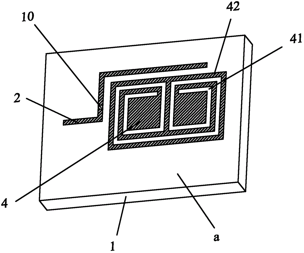
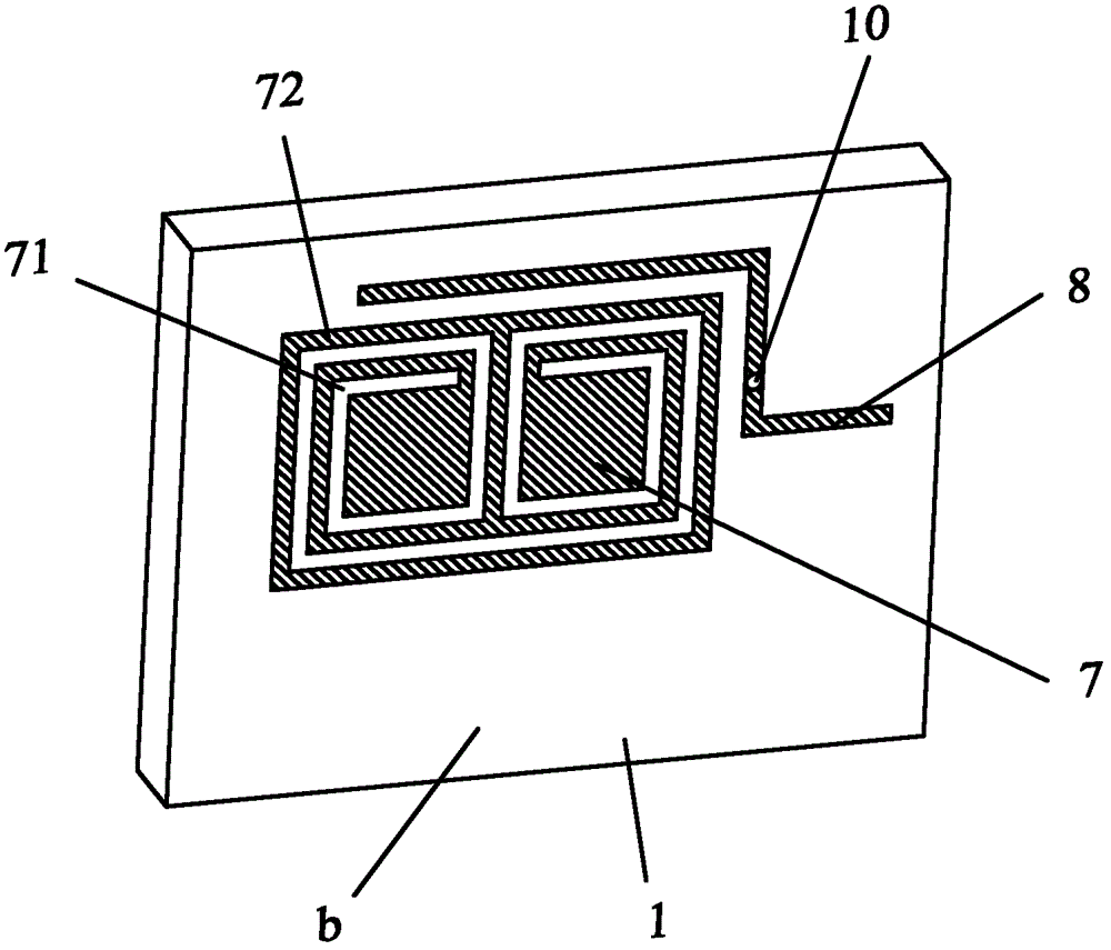
[0030] like Image 6 as shown, Image 6 It is a structural block diagram of the SIM card of the present invention. Image 6 Among them, the SIM card includes a signal sensing and receiving module 101 , a SIM card main control module 102 , a radio frequency transceiver module 103 , a metamaterial radio frequency antenna 104 and an interface module 105 . In this embodiment, the above-mentioned modules are integrally packaged in the SIM card substrate 100 . Conceivably, in order to make the space more compact, some modules may also be arranged on the opposite surface of the SIM card substrate 100 , and other modules may be arranged inside the card substrate 100 .

[0031] The signal sensing and receiving module 101 senses and receives an external signal, usually a magnetic signal, and transmits the signal to the SIM card main ...


PUM


Abstract

The invention discloses a subscriber identity module (SIM) card and a radio frequency identification system thereof. The SIM card comprises a signal induction and receiving module, an SIM card main control module, a radio frequency receiving and transmitting module, and a metamaterial radio frequency antenna, wherein the metamaterial radio frequency antenna comprises a dielectric substrate as well as a first sheet metal and a second sheet metal which are attached to two opposite surfaces of the dielectric substrate; a first feeder is arranged around the first sheet metal; a second feeder is arranged around the second sheet metal; the first feeder and the second feeder are fed into the first sheet metal and the second sheet metal in a coupling mode respectively; a first microgroove structure and a second microgroove structure are formed on the first sheet metal and the second sheet metal respectively; and the first feeder is electrically connected with the second feeder. The metamaterial radio frequency antenna is applied to the radio frequency SIM card; the size of the metamaterial radio frequency antenna is not limited to the lengths of electromagnetic waves, and an impedance matching network is not required to be configured additionally, so the antenna can be easily integrated on the SIM card; and the excellent performance and small size of the antenna are still maintained in a working frequency range of the SIM card.

Description

technical field [0001] The invention relates to the field of mobile payment, in particular to a SIM card and a radio frequency identification system thereof. Background technique [0002] With the development of the economy and the rapid changes of information technology, the number of people who own communication devices such as mobile phones in my country has reached 700 million. Adding payment functions to communication devices can reduce the inconvenience of people carrying wallets and allow people to enjoy the convenience of paying anytime and anywhere. Therefore, mobile payment has received more and more attention and has broad commercial development space in the foreseeable future . [0003] There is a problem in existing SIM cards that integrate radio frequency identification functions on SIM cards to realize mobile payment: the antenna for receiving and transmitting signals is relatively large, which cannot meet the requirements of miniaturization of SIM cards. Ac...

Claims


Application Information

Patent Timeline
Patent Type & Authority Applications(China)
IPC IPC(8): G06K19/077G06K7/00
Inventor 刘若鹏徐冠雄
Owner KUANG CHI INST OF ADVANCED TECH
Learn More