Low-inductance low loss PMSM

A permanent magnet synchronous motor, low-loss technology, applied in synchronous motors with stationary armatures and rotating magnets, electrical components, electromechanical devices, etc., can solve problems such as increased core loss, high inductance, and low no-load loss. , to achieve the effect of increasing the high speed

Inactive Publication Date: 2012-11-28
HARBIN INST OF TECH
View PDF4 Cites 2 Cited by
  • Summary
  • Abstract
  • Description
  • Claims
  • Application Information

AI Technical Summary

Problems solved by technology

Because of the above characteristics of the flywheel, the flywheel system has very high requirements for the motor/generator system, and the flywheel motor needs to have high operating speed, wide speed range, extremely low no-load loss, an

Method used


Image

  • Low-inductance low loss PMSM
  • Low-inductance low loss PMSM
  • Low-inductance low loss PMSM

Examples


specific Embodiment approach 1

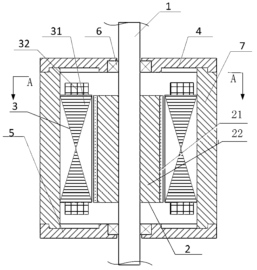
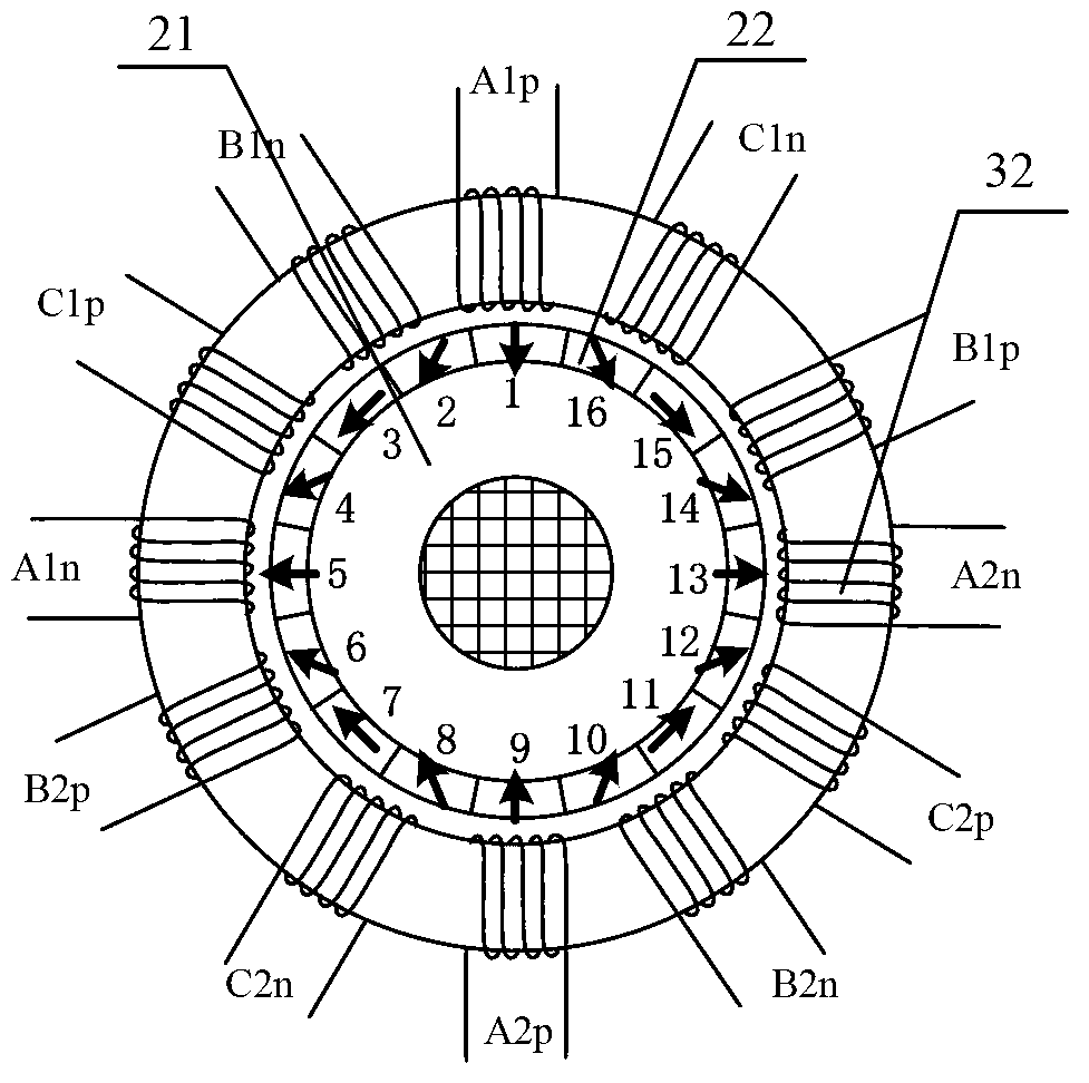
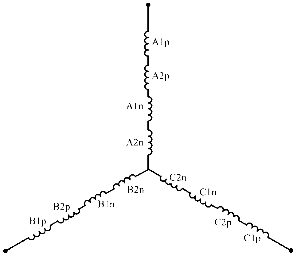
[0009] Specific implementation mode one: as figure 1 , figure 2 As shown, a low-inductance and low-loss permanent magnet synchronous motor includes a rotating shaft 1, a permanent magnet rotor 2, a stator 3, an upper end cover 4, a lower end cover 5, a bearing 6, and a housing 7. It is characterized in that the permanent magnet rotor 2 Comprising a rotor core 21 and a permanent magnet 22, the permanent magnet 22 includes a plurality of N and S poles, the N and S poles are arranged alternately or opposite to each other with the same polarity, and the permanent magnet 22 is placed on the surface of the rotor core 21 or built into the rotor core 21 Among them, the stator 3 includes a stator core 31 on which a single-phase or multi-phase stator winding 32 is radially wound, and the stator winding 32 is arranged in a circumferential direction, and each phase winding in the stator winding 32 includes one or more pairs of phases The distance between two adjacent coils is a pole pi...

specific Embodiment approach 2

[0011] Specific implementation mode two: as Figure 4 As shown, the difference between this embodiment and Embodiment 1 is that the permanent magnet rotor 2 includes two rotors, the inner rotor and the outer rotor, the inner rotor includes the inner rotor core 211 and the inner rotor permanent magnet 221, and the outer rotor includes the outer rotor core 212 and the outer rotor permanent magnet The magnet 222, the inner and outer rotors have the same number of poles, and the stator 3 is located between the inner and outer rotors. The stator winding is the same as that of Embodiment 1. In addition to the characteristics of Embodiment 1, this embodiment can effectively increase the torque of the motor by using the inner and outer windings of the stator.

specific Embodiment approach 3

[0012] Specific implementation mode three: as Figure 5 , Figure 6 , Figure 7 As shown, the difference between this embodiment and the above embodiments is that the rotor core 21 is a disc structure, the stator 3 and the rotor 2 are arranged axially, the stator core 31 is made of silicon steel sheets, and the stator core 31 is a concentric ring structure . A stator winding 32 is placed on the stator core, and its winding method and arrangement rules are the same as those in the first embodiment. The rotor magnetic field interacts with the stator current to generate torque, and the arrangement of the windings makes the motor have extremely low inductance and low core loss.


PUM


Abstract

The invention discloses a low-inductance low loss PMSM, and relates to the technical field of low-inductance low loss PMSM with a novel structure. Objective of the invention is to solve a problem that a motor in the prior art generates excessive inductance which is against high rotating speed operation of the motor, and hence generates iron core material magnetic saturation, thereby increasing iron core loss. The invention provides the low-inductance low loss PMSM, comprising a rotating shaft (1), a p-m rotor (2), a stator (3), an upper end cover (4), a lower end cover (5), a bearing (6), and a housing (7). The p-m rotor (2) comprises a rotor iron core (21) and a permanent magnet (22). The stator (3) comprises a stator iron core (31), and single-phase or polyphase stator windings (32) are radially winded on the stator iron core (31). The stator windings (32) are arranged toroidally, and each phase winding comprises a pair or a plurality of pairs of two adjacent coils. A distance between the two adjacent coils is a polar distance and the two adjacent coils are winded in opposite winding directions. The low-inductance low loss PMSM can be used in a plurality of different flywheel energy storage occasions.

Description

technical field [0001] The invention discloses a low-inductance and low-loss permanent magnet synchronous motor, which relates to the technical field of a new structure low-inductance and low-loss permanent magnet synchronous motor. Background technique [0002] The energy issue is one of the major issues facing mankind in the 21st century. While constantly developing new energy sources, advanced energy-saving technologies and energy storage technologies need to be developed in order to utilize existing energy sources more effectively. Among energy storage technologies, flywheel energy storage has high energy density, high power density, high energy conversion rate (about 90%), long service life, short charging time, adaptability to various environments, repeatable deep discharge, and simple maintenance. The advantages of green and environmental protection have broad application prospects and are also research hotspots in recent years. Among them, the motor / generator is the...

Claims


Application Information

Patent Timeline
IPC IPC(8): H02K21/14H02K3/04H02K3/28H02K16/02H02K16/00
Inventor 裴宇龙柴凤倪荣刚梁培鑫程树康
Owner HARBIN INST OF TECH
Why Eureka
Try Eureka