
Optical fiber time frequency hybrid transmission method

A time-frequency, optical fiber technology, applied in the field of optical fiber time-frequency hybrid transmission, to achieve the effect of convenient cascading, high stability, and short-term stability assurance

Inactive Publication Date: 2012-11-28
PLA UNIV OF SCI & TECH
View PDF4 Cites 24 Cited by
  • Summary
  • Abstract
  • Description
  • Claims
  • Application Information

AI Technical Summary

Problems solved by technology

[0003] At present, the methods of using optical fiber for time synchronization include the pre-compensation method and the two-way time comparison method. The existing methods are to measure the clock difference between the time-frequency central station and the terminal station and compensate it, and the terminal user can only obtain time synchronization. signal, i.e. synchronous second pulse signal

Method used


Image

  • Optical fiber time frequency hybrid transmission method
  • Optical fiber time frequency hybrid transmission method
  • Optical fiber time frequency hybrid transmission method

Examples


Embodiment Construction

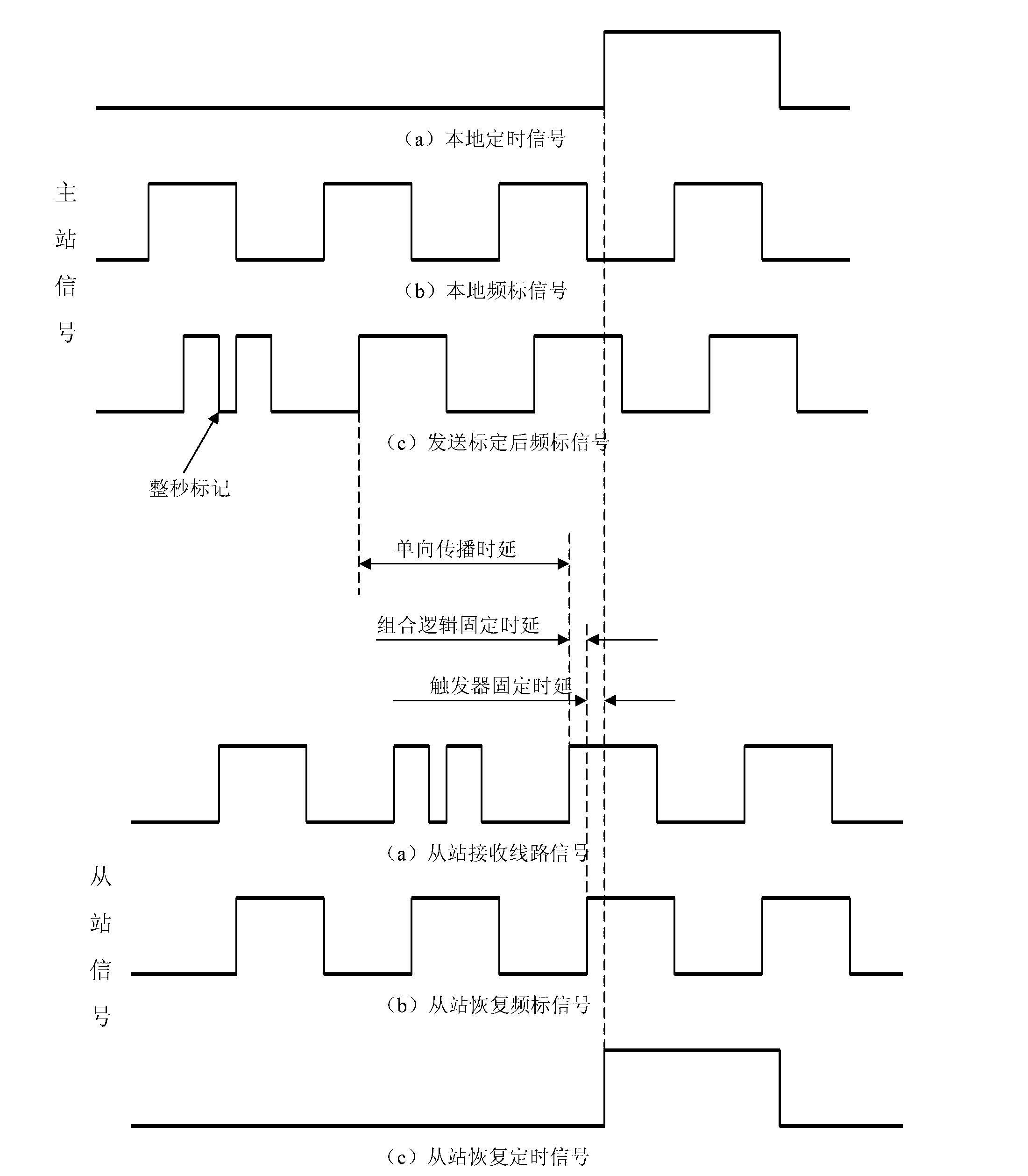
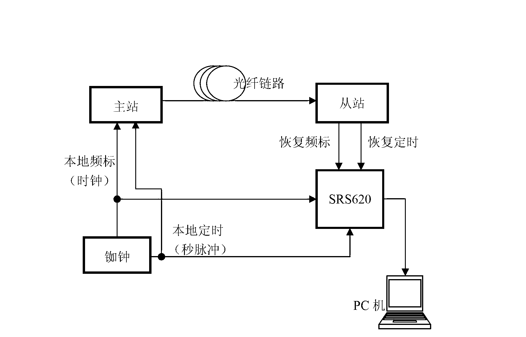
[0017] (a). Full-second calibration: The master station normally transmits a 10MHz frequency signal to the slave station, and performs special calibration in the 10MHz period of the whole second. The calibration method diagram is shown in figure 1 . After the slave station recognizes the special calibration, remove the mark and restore the normal frequency signal, which is the required frequency standard signal. And take the frequency standard as the clock, and get the timing signal at the second edge of the marking period to complete the time service. While recovering the frequency scale and time scale signals, the slave station returns the received time-frequency mixed transmission signal to the master station as it is, for the loopback delay measurement of the master station.

[0018] (b). Loopback delay measurement: The master station recovers the timing signal from the backhaul signal according to the above method of the slave station, and uses the internal time interva...


PUM


Abstract

The invention discloses an optical fiber time frequency hybrid transmission method. The method comprises the following steps that: a master station normally transmits a 10MHz frequency signal to a slave station, a narrow negative pulse is interpolated into a previous periodic signal high level within a whole second, and the frequency signal is calibrated in the whole second; the slave station restores the frequency signal by employing combinational logic and restores a timing signal through a trigger after identifying special calibration; the slave station simultaneously returns the received time frequency hybrid transmission signal to the master station in an original sample mode, wherein the hybrid transmission signal is used for the loopback time delay measurement of the master station; the master station restores the timing signal from the returned signal according to the method of the slave station, dynamically measures the time delay of the restored timing signal and a local timing signal, and combines with the fixed time delay of the equipment to calculate the phase precompensation of a frequency scale signal in one second; and the master station realizes uniform phase compensation in the next second by utilizing the calculated phase compensation, so that the restored frequency and timing signal of the slave station are synchronous with those of the master station. The optical fiber time frequency hybrid transmission method has the advantages of time service precision, low cost, convenient cascade connection and plug and play function.

Description

technical field [0001] The method relates to a method of using optical fiber links for frequency and time mixed transmission to realize simultaneous time service and frequency transmission in different places (hereinafter referred to as the time-frequency mixed transmission method). The method has the advantages of high precision, low cost, convenient cascading, and plug-and-play. Background technique [0002] All major countries in the world are actively developing their own high-precision time and frequency unified systems. The more famous ones are mainly space-based systems, such as the GPS system in the United States, the GLONASS in Russia, the Galileo system in Europe, and the Beidou system under construction in my country. At the same time, the high-precision time-frequency network based on the optical network is also an important part of building a time-frequency system. It is not only capable of high-precision time-frequency transmission, but also complements and sup...

Claims


Application Information

Patent Timeline
Patent Type & Authority Applications(China)
IPC IPC(8): H04B10/08H04B10/12
Inventor 吴传信卢麟经继松朱勇张宝富王荣
Owner PLA UNIV OF SCI & TECH
Learn More