Directional heat conduction pcb board and electronic equipment

A PCB board, directional heat conduction technology, applied in the direction of circuit substrate materials, printed circuit components, etc., can solve the problems of upward heat conduction, uneven heat conduction, large thermal resistance coefficient, etc.

Active Publication Date: 2015-10-07
KUANG CHI INST OF ADVANCED TECH
View PDF7 Cites 0 Cited by
  • Summary
  • Abstract
  • Description
  • Claims
  • Application Information

AI Technical Summary

Problems solved by technology

Furthermore, since VLSI and discrete components with high heat generation performance, such as integrated chips and LEDs, have higher and higher requirements for heat dissipation performance, ordinary printed circuit boards cannot change the conventional upward heat conduction mode, and the heat conduction is uneven. Large thermal resistance coefficient

Method used


Image

  • Directional heat conduction pcb board and electronic equipment
  • Directional heat conduction pcb board and electronic equipment
  • Directional heat conduction pcb board and electronic equipment

Examples


Embodiment Construction

[0018] Please refer to figure 1 , is a schematic diagram of the electronic device of the present invention. The electronic device includes a certain heat conduction PCB board 10 arranged in its casing. The directional heat conduction PCB board 10 is used to replace the traditional PCB board to carry several electronic components, such as resistors, capacitors, integrated circuits (ICs) and so on. In this embodiment, the electronic equipment includes, but is not limited to, electronic devices such as various consumer electronic equipment, network servers, radio frequency equipment, and electronic communication equipment.

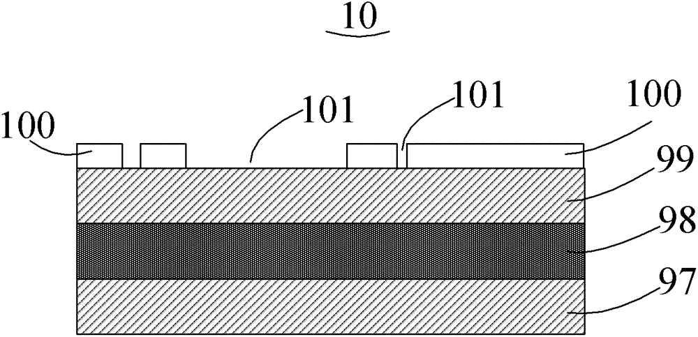
[0019] Please refer to figure 2 , the directional heat conduction PCB board 10 includes a first metal layer 97 , a heat conduction medium layer 98 , a second metal layer 99 and a copper clad layer 100 . The copper clad layer 100 and the heat conduction medium layer 98 are respectively disposed on two sides of the second metal layer 99 , and the first meta...


PUM


Abstract

The invention relates to a directional heat conduction PCB (printed circuit board), comprising a first metal layer, a heat conduction dielectric layer, a second metal layer and a copper layer, wherein the copper layer and the heat conduction dielectric layer are respectively arranged on the two sides of the second metal layer, and the first metal layer is arranged on one side of the heat conduction dielectric layer relative to the second metal layer. The electronic equipment adopts the directional heat conduction PCB, and thus heat dissipation of a circuit of the whole electronic equipment is changed into a downward heat conduction manner from a conventional upward heat conduction manner; and heat conduction is uniform, and thermal resistivity is low. The invention also provides electronic equipment applying the directional heat conduction PCB.

Description

technical field [0001] The invention relates to a heat-conducting PCB board for electronic equipment, in particular to a directional heat-conducting PCB board and electronic equipment. Background technique [0002] At present, the widely used PCB boards are copper-clad / epoxy glass cloth substrates or phenolic resin glass cloth substrates, and there are also a small amount of paper-based copper-clad boards. Although these substrates have excellent electrical properties and processing properties, they have poor heat dissipation. As a heat dissipation path for high-heating components, it is almost impossible to expect the heat to be conducted by the resin of the PCB itself, but to dissipate heat from the surface of the component to the surrounding air. However, as electronic products have entered the era of component miniaturization, high-density installation, and high-heating assembly, it is not enough to rely solely on the surface of components with a very small surface area ...

Claims


Application Information

Patent Timeline
Patent Type & Authority Patents(China)
IPC IPC(8): H05K1/05
Inventor 刘若鹏徐冠雄吕晶史世东
Owner KUANG CHI INST OF ADVANCED TECH
Why Eureka
Try Eureka