Device and method for axial loading to assist bulging of magnetic pulse pipe

A technology of axial loading and auxiliary magnetic, which is applied in the field of magnetic pulse tube bulging device, can solve the problems of uneven deformation, cracking and excessive thinning of the tube wall, so as to increase the forming limit, improve the formability and improve the axial The effect of mobility

Active Publication Date: 2012-12-05
HARBIN INST OF TECH
View PDF5 Cites 32 Cited by
  • Summary
  • Abstract
  • Description
  • Claims
  • Application Information

AI Technical Summary

Problems solved by technology

[0005] The object of the present invention is to provide a device and method for axially loading assisted magnetic pulse tube bulging to solve the problems of uneven deformation of the tube wall and excessive reduction in the local bulging process of the tube using the existing magnetic pulse forming technology. Problems such as being thin enough to break

Method used


Image

  • Device and method for axial loading to assist bulging of magnetic pulse pipe
  • Device and method for axial loading to assist bulging of magnetic pulse pipe
  • Device and method for axial loading to assist bulging of magnetic pulse pipe

Examples


specific Embodiment approach 1

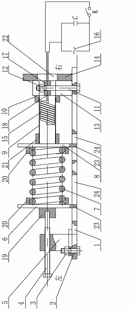
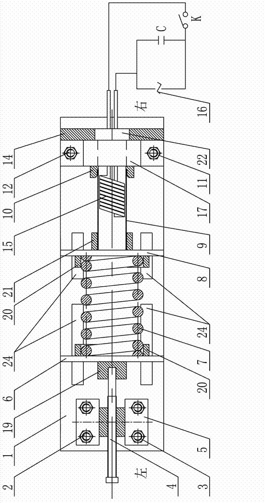
[0018] Specific embodiment one: combine 1 and figure 2 Explain that the device for axial loading assisted magnetic pulse tube bulging in this embodiment includes a rectangular bottom plate 1, a screw 4, a screw guide block 5, two push plates, a spring 7, a pipe stopper 10, Fixture 13, baffle plate 14, coil 15, power supply 16, lead screw limit sleeve 19, pipe fitting sheath 21, capacitor bank C, discharge control switch K and two spring limit sleeves 20; two push plates are respectively left Push plate 6 and right push plate 8, fixture is made up of upper clamp block 17 and lower clamp block 18,

[0019] Lead screw guide block 5, two push plates, fixture 13 and baffle plate 14 are arranged side by side on the rectangular base plate 1 successively from left to right along the length direction of rectangular base plate 1, lead screw guide block 5 (through four first bolts 2 and four first nuts 3) are detachably connected to the rectangular bottom plate 1, the baffle plate 14 i...

specific Embodiment approach 2

[0020] Specific implementation mode two: combination figure 1 and figure 2 Note that the coil 15 in this embodiment is composed of a single wire wound spirally on the coil frame for multiple turns, and two adjacent turns of the wire are separated by a high-voltage insulating material, and the surface of the coil 15 is made of a high-voltage insulating material (such as polyimide film or epoxy glass cloth) covered. The undisclosed technical features in this embodiment are the same as those in the first embodiment.

specific Embodiment approach 3

[0021] Specific implementation mode three: combination figure 1 and figure 2 Description, the spring 7 in this embodiment is made of 60Si 2 Made of Mn material. With such a design, a relatively large axial preload is required to affect the bulging of the pipe fitting 9, while 60Si 2 Mn material has good elasticity and good tempering stability, and is suitable for large-load springs. The undisclosed technical features in this embodiment are the same as those in the first embodiment.


PUM

PropertyMeasurementUnit
capacitanceaaaaaaaaaa

Abstract

The invention discloses a device and a method for axial loading to assist bulging of a magnetic pulse pipe, relates to a device and a method for bulging of a magnetic pulse pipe, and aims to solve the problem of breakage due to the fact that when a pipe fitting is locally bulged by existing magnetic pulse forming technology, deformation of a pipe wall is uneven and the pipe wall is excessively thinned. A lead guiding block is connected with a rectangular bottom plate, an upper clamp block and a lower clamp block are connected with the rectangular bottom plate, a lead screw is connected with the lead screw guiding block in a threaded manner, bumps on two push plates are slidably arranged in guide grooves of the rectangular bottom plate, the right end of the lead screw is arranged in a lead screw limiting sleeve fixedly connected with the left push plate, a spring is arranged in spring limiting sleeves fixedly connected with the two push plates, a coil is arranged between the right push plate and a fixture, two lead wire sections of the coil are serially connected onto a discharge control switch, and a capacitor bank is serially connected with a power source. The method includes sleeving a pipe fitting on the coil; exerting axial pre-tightening force; and taking out the formed pipe fitting after discharge forming. The device and the method are used for bulging and machining pipe fittings difficult to form.

Description

technical field [0001] The invention relates to a device and method for bulging a magnetic pulse tube. Background technique [0002] With the development of modern industry and science and technology, people have higher and higher requirements on the performance of materials, and the precise forming and processing of some difficult-to-form materials has become a technical problem to be solved urgently. In recent years, in order to effectively reduce energy consumption and reduce environmental pollution, lightweight has become the mainstream trend of modern structural design. The application of lightweight, high-strength and difficult-to-form materials represented by aluminum alloys in advanced manufacturing fields such as automobiles and aerospace vehicles increasing day by day. However, it is well known that aluminum alloys have poor room temperature deformability. When the quasi-static deformation of aluminum alloy is processed by ordinary stamping technology, its formin...

Claims


Application Information

Patent Timeline
Patent Type & Authority Applications(China)
IPC IPC(8): B21D26/14
Inventor 于海平陈洁李杰徐俊瑞崔俊佳李春峰
Owner HARBIN INST OF TECH
Why Eureka
Try Eureka