Continuous oil tube with gradually changed wall thickness and manufacturing method thereof

A manufacturing method and oil pipe technology, which can be applied to drill pipes, casings, and earth-moving drilling, etc., can solve the problems of large differences in performance between welds and base metals, failures, etc. , the effect of increasing safety

Active Publication Date: 2012-12-05
BC P INC CHINA NAT PETROLEUM CORP +1
View PDF4 Cites 3 Cited by
  • Summary
  • Abstract
  • Description
  • Claims
  • Application Information

AI Technical Summary

Problems solved by technology

[0006] At present, the pipe-tube butt welding of finished coiled tubing with different specifications can realize the variable wall thickness requirements of coiled tubing. The wall thickness of the pipe is closely related. Whether manual welding or automatic welding is used, the stepped joint will be formed. The performance of the weld and the base metal is quite different. When deformation occurs, it is easy to fail prematurely at the girth weld due to the different deformation of each part.

Method used


Image

  • Continuous oil tube with gradually changed wall thickness and manufacturing method thereof
  • Continuous oil tube with gradually changed wall thickness and manufacturing method thereof

Examples


Embodiment Construction

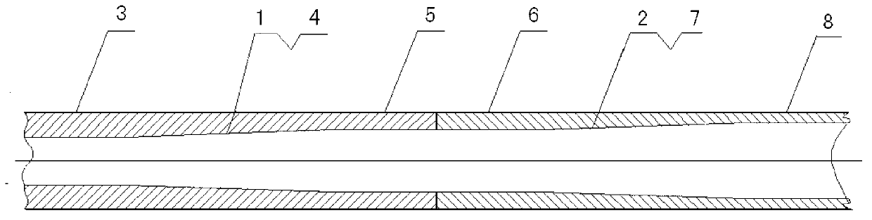
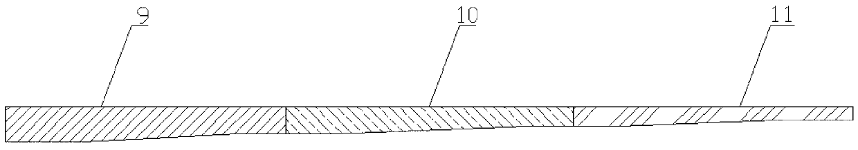
[0023] Attached below Figure 1-2 Embodiments of the present invention are described in detail.

[0024] A coiled tubing with gradually changing wall thickness is formed by at least one section of wall thickness gradually changing pipe I1 and a section of wall thickness gradually changing pipe II2 butted end to end, the head end of the wall thickness gradually changing pipe I1 is a constant wall thickness joint section I3, and the middle part is a variable wall thickness Section I4, the tail end is equal-wall-thickness joint section II5; the head end of the wall-thickness gradient pipe II2 is equal-wall-thickness joint section III6, the middle part is variable-wall-thickness section II7, and the tail end is equal-wall-thickness joint section IV8; The constant wall thickness joint section II5 is docked with the constant wall thickness joint section III6, and the constant wall thickness joint section II5 has the same wall thickness as the constant wall thickness joint section II...


PUM

PropertyMeasurementUnit
thicknessaaaaaaaaaa
yield strengthaaaaaaaaaa
tensile strengthaaaaaaaaaa

Abstract

The invention relates to a continuous oil tube with a gradually changed wall thickness and a manufacturing method thereof; the continuous oil tube at least comprises a section of pipe I with the gradually changed wall thickness and a section of pipe II with the gradually changed wall thickness which are connected end to end; the first end of the pipe I with the gradually changed wall thickness is a connector section I with equal wall thickness, the middle part of the pipe I is a section I with the changed wall thickness, and the tail end of the pipe I is a connector section II with equal wall thickness; the first end of the pipe II with the gradually changed wall thickness is a connector section III with equal wall thickness, the middle part of the pipe II is a section II with the changed wall thickness, and the tail end of the pipe II is a connector section IV with equal wall thickness; the connector section II with equal wall thickness is butted with the connector section III with equal wall thickness, and the wall thickness of the connector section II with equal wall thickness is the same with that of the connector section III with equal wall thickness; and the wall thicknesses of the section I with the changed wall thickness and the section II with the changed wall thickness from the first ends to the tail ends are gradually reduced. According to the invention, the oil tube is made of a steel strip with the gradually changed thickness along a length direction, so that the wall thickness of the continuous oil tube is gradually changed continuously in the length direction, the self-weight of the continuous oil tube is reduced under equal length, the pulling force on the continuous oil tube in a wellhead section is reduced, and the operation depth of the continuous oil tube and the operation safety are improved.

Description

technical field [0001] The invention relates to the technical field of oil and gas pipes, in particular to a coiled oil pipe with gradually changing wall thickness and a manufacturing method thereof. Background technique [0002] Coiled tubing has been widely used in oil field workover, drilling, completion, logging, stimulation and other fields in the oil and gas industry. Due to the advantages of high efficiency, low cost, wide operation range and small footprint in the above operations, coiled tubing technology has developed rapidly in recent years. [0003] During use, the coiled tubing needs to be led out from the reel, and enter and hang in the wellbore through the guide arch (gooseneck) and injection head. For shallow wells with small depth, ordinary coiled tubing can meet the requirements. However, when the coiled tubing is used in deep or ultra-deep wells, the suspension weight and lifting force of the coiled tubing will increase significantly as the running depth...

Claims


Application Information

Patent Timeline
Patent Type & Authority Applications(China)
IPC IPC(8): E21B17/20B21C37/08
Inventor 杨忠文毕宗岳鲜林云张锦刚余晗李博锋张晓峰汪海涛
Owner BC P INC CHINA NAT PETROLEUM CORP
Why Eureka
Try Eureka