Synchronously operating jet type bottle cavity drying device and method

A technology of synchronous operation and drying device, which is applied to the drying field of the inner cavity of food packaging containers, can solve the problems of no air drying, short drying time, poor drying effect, etc., and achieves saving hot air source, good drying effect and drying effect. effect of time extension

Inactive Publication Date: 2012-12-05
GUANGZHOU NANLIAN IND
View PDF8 Cites 4 Cited by
  • Summary
  • Abstract
  • Description
  • Claims
  • Application Information

AI Technical Summary

Problems solved by technology

[0006] However, in practical application, this drying method has obvious defects: since the nozzle is fixed, the bottle runs above it and passes through each nozzle in turn. Only when the bottle mouth is aligned with the nozzle can it be blown by the hot air flow, leaving There is no air-drying effect from one nozzle to the next nozzle
Therefore, in this air-drying process, the jet air flow received by the bottle is actually an intermittent form, the effective drying time is very short, and the drying effect is not good
Especially for small-mouth bottles, there are less chances and time for the jet air to blow into the bottle cavity, and the drying effect is worse

Method used


Image

  • Synchronously operating jet type bottle cavity drying device and method
  • Synchronously operating jet type bottle cavity drying device and method
  • Synchronously operating jet type bottle cavity drying device and method

Examples


Embodiment

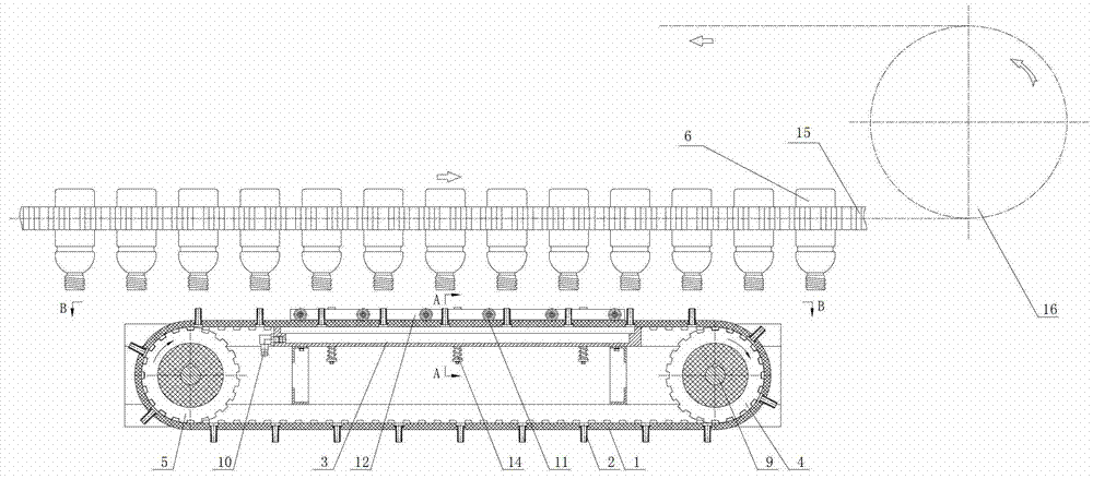
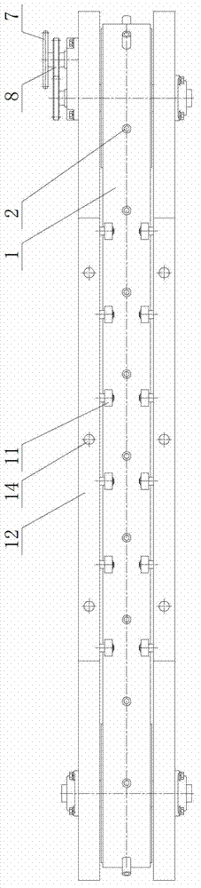
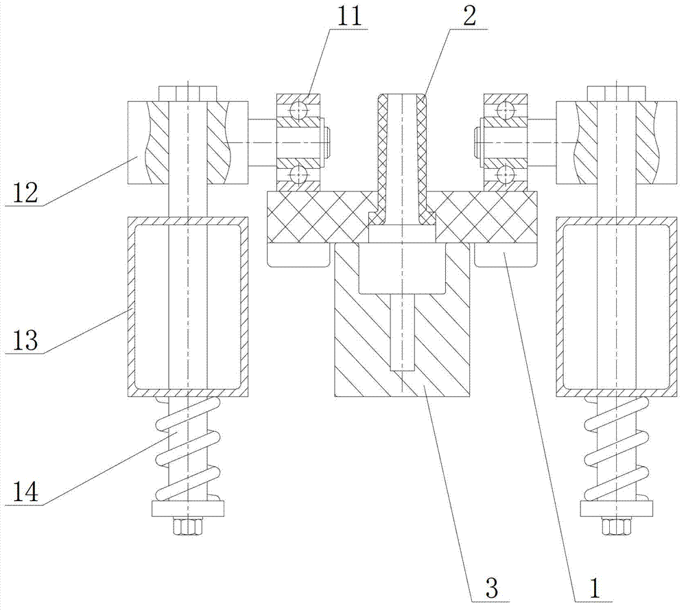
[0041] In this embodiment, a synchronously running spray type bottle chamber drying device, such as figure 1 or figure 2 As shown, it includes a synchronously running bottle clamping mechanism and a synchronous belt spraying mechanism. The bottle clamping mechanism is arranged above the timing belt spraying mechanism; 2 and long groove air chamber 3, the two ends of the synchronous belt are respectively connected with the synchronous belt pulley, the synchronous belt wheel at one end is used as the driving wheel 4, and the synchronous belt wheel at the other end is used as the driven wheel 5, and the driving wheel is connected with the synchronous belt drive assembly , a plurality of nozzles 2 are distributed on the timing belt 1, and the long groove air chamber 3 is located under the timing belt between the two timing pulleys, and each nozzle 2 above the long groove air chamber is clamped with the bottle clamping mechanism. The 6 bottle mouths of each bottle held correspond...


PUM


Abstract

The invention discloses a synchronously operating jet type bottle cavity drying device and a synchronously operating jet type bottle cavity drying method. The synchronously operating jet type bottle cavity drying device comprises a bottle clamping mechanism and a synchronous belt jet mechanism which operate synchronously. The synchronous belt jet mechanism comprises a synchronous toothed belt, synchronous pulleys, a synchronous toothed belt driving assembly, jet nozzles and an elongated slot air chamber. The two sides of the synchronous toothed belt are respectively connected with the synchronous pulleys which serve as driving wheels and are connected with the synchronous toothed belt driving assembly. A plurality of jet nozzles are distributed on the synchronous toothed belt. The elongated slot air chamber is arranged below the synchronous toothed belt between the two synchronous pulleys. The jet nozzles located above the elongated slot air chamber correspond to the openings of the bottles one by one. The method includes the steps that the bottle clamping mechanism and the synchronous belt jet mechanism operate synchronously and the jet nozzles above the elongated slot air chamber are aligned with the openings of the bottles one by one to continuously jet hot air for drying. The synchronously operating jet type bottle cavity drying device overcomes the disadvantages of short effective drying time, low efficiency and poor drying effect in the cavity of the bottle of a conventional hot air injection device, and achieves the purpose of drying the cavity of the bottle quickly and efficiently.

Description

technical field [0001] The invention relates to a drying technology for the inner cavity of a food packaging container, in particular to a synchronously operating spray-type bottle cavity drying device and method. Background technique [0002] In the production process of food cans, packaging containers (including plastic bottles, glass bottles, metal cans, etc.) need to be cleaned and dried before filling. Only in this way can products meet food hygiene requirements and product quality. Therefore, whether the cleaning and drying process of the packaging container is perfect and whether the related equipment has excellent performance will directly affect the quality of the food after packaging. [0003] In the production process of cans, especially condiments, there are strict requirements on the amount of residual water in the packaging container. For example, the packaging bottles of oil consumption, seasoning sauce and other products must be thoroughly dried after cleanin...

Claims


Application Information

Patent Timeline
Patent Type & Authority Applications(China)
IPC IPC(8): F26B21/00F26B25/02
Inventor 张聪沈建华吴柏毅李艳平
Owner GUANGZHOU NANLIAN IND
Why Eureka
Try Eureka