Combined type magnetic core and preparation method thereof

A composite, magnetic core technology, used in inductor/transformer/magnet manufacturing, inorganic material magnetism, electrical components, etc., can solve problems such as difficult molds, sedimentation, and colloid bubbles, and achieve the effect of avoiding bubbles and uneven magnetic properties

Inactive Publication Date: 2012-12-05
美桀电子科技(深圳)有限公司
View PDF8 Cites 15 Cited by
  • Summary
  • Abstract
  • Description
  • Claims
  • Application Information

AI Technical Summary

Problems solved by technology

[0005] However, it is easy to generate air bubbles in the colloid when filling the mold with the colloid mixed with magnetic powder, and it is difficult to make the mold a vacuum
In addition, the magnetic powder has a relatively large specific gravity relative to the colloid, and sedimentation will occur in the colloid, resulting in uneven magnetic distribution of the coated body.

Method used


Image

  • Combined type magnetic core and preparation method thereof
  • Combined type magnetic core and preparation method thereof
  • Combined type magnetic core and preparation method thereof

Examples


no. 1 example

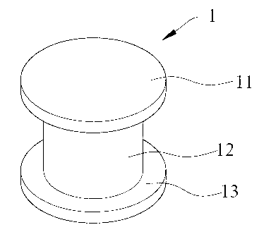
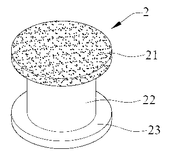
[0023] See Figure 2A . The magnetic core 2 includes an upper end portion 21, a columnar portion 22, and a lower end portion 23. The upper end portion 21 and the lower end portion 23 are formed at both ends of the columnar portion 22, and the vertical columnar portion 22 of the upper end portion 21 and the lower end portion 23 extends in the direction The cross-sectional area may be larger than the cross-sectional area of ​​the columnar portion 22 perpendicular to its extending direction, forming a magnetic core similar to the Chinese "工" or English "I" shape.

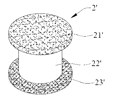
[0024] At least one of the upper end 21 and the lower end 23 can be made of a mixture of powdered magnetic material and powdered adhesive in a predetermined ratio, and formed on both ends of the columnar portion 22. Such as Figure 2A As shown, the upper end 21 of the magnetic core 2 is made of a mixture, and is bonded to one end of the columnar portion 22 by heating. Alternatively, the lower end portion 23 may also be m...

no. 2 example

[0036] See Figure 4 The magnetic core 5 includes a core material 51 and a covering body 52 covering the core material 51. The core material 51 is annular and has a hollow portion 510, and the core material 51 has a gap 511. The covering body 52 is made of a mixture of powdered magnetic material and a powdery adhesive. The covering body 52 covers the core material 51 and has a hole 520 penetrating through the hollow portion 510 of the core material 51. In other words, the covering body 52 coaxially covers the entire core material 51 and has a through hole 520 formed along the axis of the core material 51.

[0037] Opening a gap 511 on the (ring-shaped) core material 51 can change the hysteresis curve of the core material 51. Using the (ring-shaped) core material 51 with the gap 511 to make an inductor can obtain better inductance characteristics, but the magnetic field lines will be at the gap 511 Exposure causes eddy current loss, increased magnetic resistance, and decreased per...


PUM


Abstract

The invention provides a combined type magnetic core and a preparation method thereof. The method comprises the following steps: firstly, mixing powdery magnetic materials and a powdery adhesive agent in a presetting proportion so as to form a solid mixture; secondly, putting a column-shaped core material into a column-shaped holding mold of a mould; filling the mixture into the upper and the lower ends of the mould respectively so as to form a mold, or putting the mixture, an annular core material and the mixture into another mould in sequence; and subsequently, heating the mould or the solid mixture in another mould to enable the powdery magnetic materials to be mutually bonded through the powdery adhesive agent so as to be shaped at two ends of the column-shaped core material, or enable the powdery magnetic materials to be mutually bonded through the powdery adhesive agent so as to be wrapped outside the whole annular core material coaxially and form a through holes around the axis of the annular core material. Therefore, with the adoption of the preparation method, the magnetic cores containing more than two materials can be produced.

Description

Technical field [0001] The invention relates to a composite magnetic core and a manufacturing method thereof, in particular to a composite magnetic core applied to an inductor, a transformer or a filter and a manufacturing method thereof. Background technique [0002] Magnetic cores can be used in inductors, filters or transformers in various electronic devices. At present, there are roughly two methods for making magnetic cores: powder pressing process or magnetic glue system process. [0003] In terms of the powder pressing process, the powder material is pressed into a magnetic core through high temperature and high pressure, such as figure 1 Magnetic core 1 shown. The manufacturing method is to first fill the magnetic powder into the mold, and then apply a large pressure to the mold to press the magnetic powder into a shape. However, the cost of the process equipment that can provide huge pressure and the mold that can withstand the huge pressure is very high. In addition, wh...

Claims


Application Information

Patent Timeline
Patent Type & Authority Applications(China)
IPC IPC(8): H01F27/255H01F1/22H01F41/02B22F3/00
Inventor 谭隆竞罗鹏程
Owner 美桀电子科技(深圳)有限公司
Why Eureka
Try Eureka