
Deep hole drilling device

A technology of drilling depth and bit, which is applied in the direction of boring/drilling, drilling/drilling equipment, drilling repair, etc. It can solve the problems of insufficient cooling and chip removal when drilling deep holes, and achieve sufficient cooling and removal. The effect of crumbs

Inactive Publication Date: 2012-12-12
TAIYUAN HEAVY IND
View PDF5 Cites 7 Cited by
  • Summary
  • Abstract
  • Description
  • Claims
  • Application Information

AI Technical Summary

Problems solved by technology

[0003] The purpose of the present invention is to provide a deep hole processing device to solve the problem of insufficient cooling and chip removal in the prior art when drilling deep holes
[0005] The present invention forms a circulating passage between the oil feeder, the internal chip removal drill bit, the internal chip removal drill rod, and the chip conveyor, so that the entire device can be fully cooled during the drilling process, and at the same time, the function of chip removal can be realized , which solves the problem of insufficient cooling and chip removal when drilling deep holes in the prior art

Method used


Image

  • Deep hole drilling device
  • Deep hole drilling device
  • Deep hole drilling device

Examples


Embodiment Construction

[0011] Specific embodiments of the present invention will be described in detail below in conjunction with the accompanying drawings. It should be understood that the specific embodiments described here are only used to illustrate and explain the present invention, and are not intended to limit the present invention.

[0012] This embodiment is illustrated by taking the deep hole drilling device combined with a boring machine as an example. It should be understood that the deep hole drilling device of the present invention can be used in combination with a power head, a feeding device, etc., and is not limited thereto.

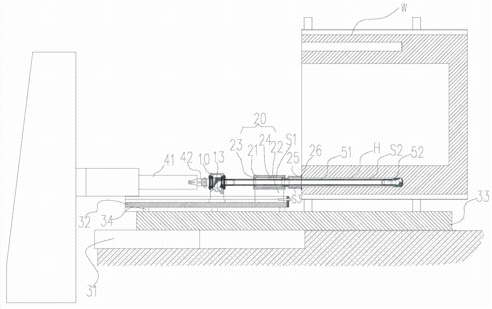
[0013] like figure 1 As shown, the deep hole drilling device includes a chip conveyor 10, an oil feeder 20 and a drilling part. The chip conveyor 10 and the oil feeder 20 are slidably arranged on the guide ram 32 on the worktable 31 . An additional workbench 33, an adjustment pad 34, etc. can also be added between the workbench 31 and the guide ram 32 to mat...


PUM


Abstract

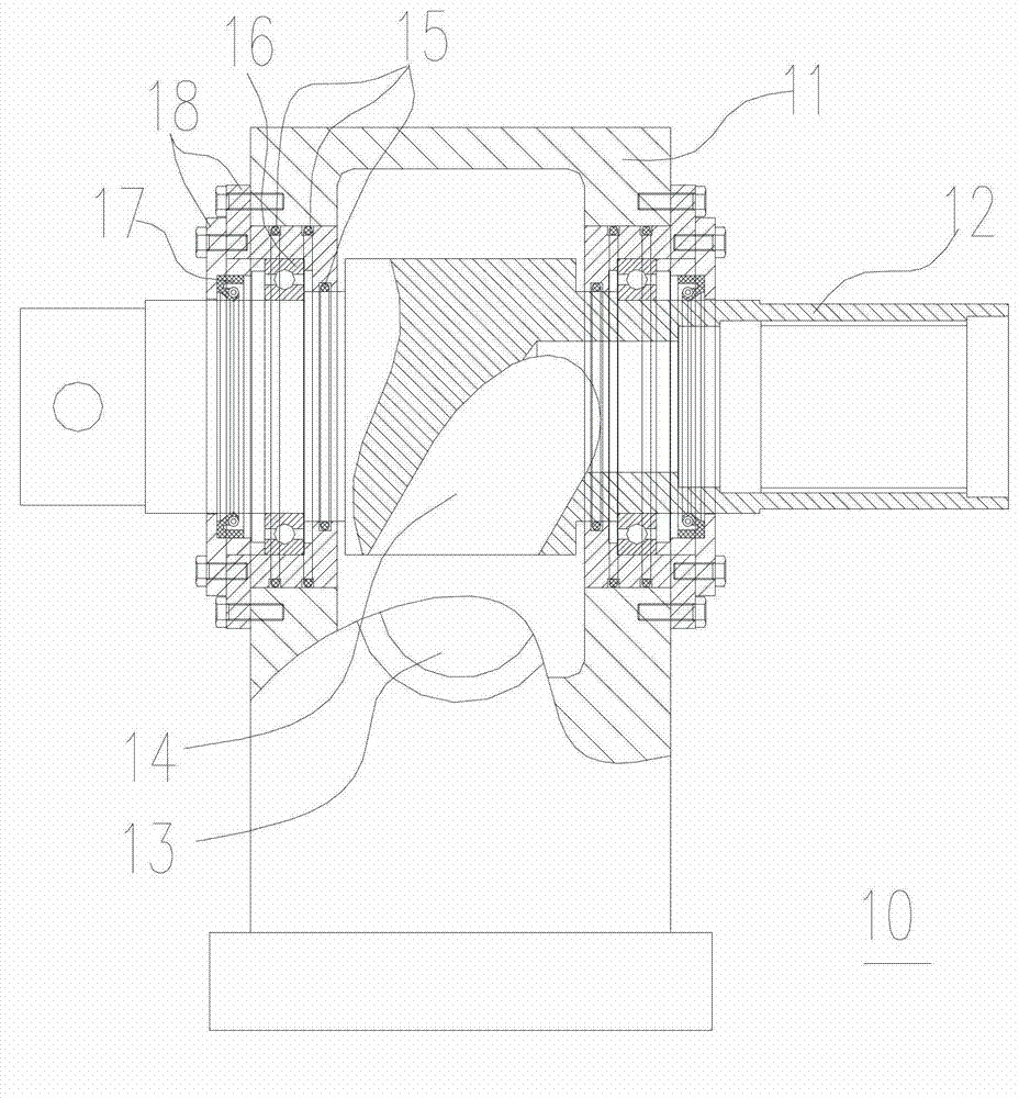
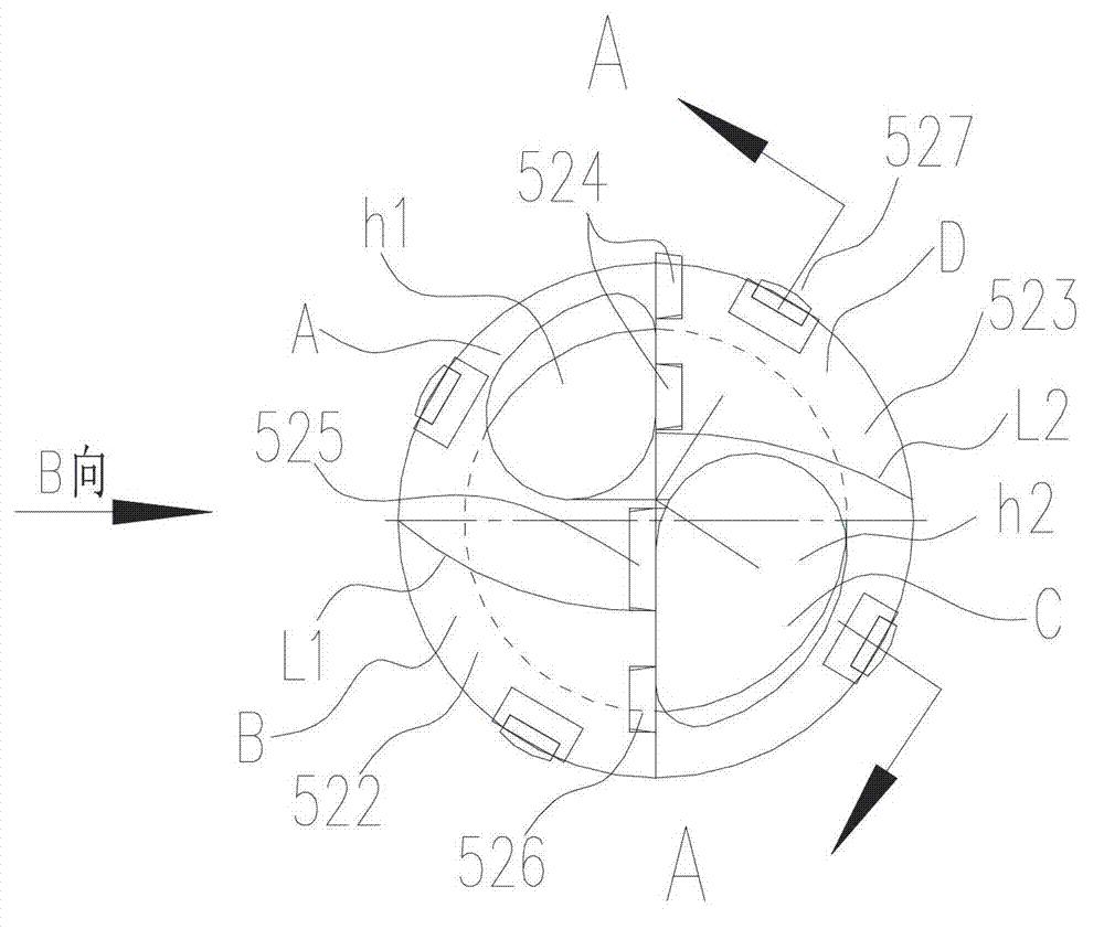
A deep hole drilling device comprises a chip cleaner, an oil feeder and a hole drilling portion. The chip cleaner comprises a body and a connecting shaft, the connecting shaft is provided with a chip removing channel, and a chip removing hole is arranged on the body and is communicated with the chip removing channel; the hole drilling portion comprises an inner chip removing drill stem and an inner chip removing drill bit connected with the inner chip removing drill stem, the inner chip removing drill bit is provided with drill bit chip removing holes, the inner chip removing drill stem is a hollow stem, one end of the inner chip removing drill stem is connected with the connecting shaft, and the inner chip removing drill stem is communicated with the chip removing channel; and the oil feeder is sleeved on the outer portion of the inner chip removing drill stem, a first space is formed between the oil feeder and the inner chip removing drill stem, and an oil inlet is arranged on the oil feeder. When the hole drilling portion is drilled in a processed workpiece, a second space is formed between the outer wall of a drilled portion of the inner chip removing drill stem and the wall of a drilled hole, cooling liquid from the oil inlet sequentially flows through the first space and the second space, flows into the inner chip removing drill stem via the drill bit chip removing holes, and then flows into the chip removing channel, and then the cooling liquid and chips generated during hole drilling are mixed with each other and are drained via the chip removing hole.

Description

technical field [0001] The invention relates to a deep hole processing device, in particular to a deep hole drilling device. Background technique [0002] With the development of large-scale mechanical manufacturing equipment, it is often necessary to process deep holes with large diameters on large boxes. However, when processing deep holes, there are many internal cooling and chip removal processes, and the effect is not good, and the cooling and chip removal components complex structure. And, usually owing to be subjected to the restriction of existing processing equipment, make the deep hole on the large box body difficult to process. Therefore, it is necessary to provide a deep hole machining device capable of adequate cooling and chip removal, so as to facilitate the deep hole machining of large equipment boxes. Contents of the invention [0003] The object of the present invention is to provide a deep hole machining device to solve the problem of insufficient cool...

Claims


Application Information

Patent Timeline
Patent Type & Authority Applications(China)
IPC IPC(8): B23B41/02B23B47/00B23B51/00B23Q11/00
Inventor 常思伟赵萍崔春艳
Owner TAIYUAN HEAVY IND
Learn More