Blade pump with telescopic and controllable blades

A technology of vane telescopic and vane pumps, which is applied in the direction of pumps, rotary piston pumps, rotary piston machines, etc., can solve the problems that the rotation stability of the rotor cannot be guaranteed, affects the rotor transmission in the vane pump, and affects the service life of hydraulic oil, etc. Achieve the effect of maintaining the physical properties, reducing the connection structure and improving the service life

Active Publication Date: 2012-12-12
胡阳
View PDF6 Cites 1 Cited by
  • Summary
  • Abstract
  • Description
  • Claims
  • Application Information

AI Technical Summary

Problems solved by technology

In the above cases, if the vane pump continues to work effectively, on the one hand, it will increase energy consumption, and on the other hand, because the hydraulic oil in the entire hydraulic pipeline stops flowing, the vane will stop the flow of the remaining fluid in the cavity of the vane pump. A small part of the hydraulic oil is continuously agitated, which will bring about changes in the physical characteristics of the part of the hydraulic oil, such as a decrease in viscosity and an increase in temperature, which in turn will increase the temperature of the vane pump
The physical parameters of the entire hydraulic oil system vary greatly, which will affect the overall service life of the hydraulic oil in the long run
If the rotor is stopped under the above conditions by setting a clutch, on the one hand, the structure of the vane pump will be complicated; Not guaranteed

Method used


Image

  • Blade pump with telescopic and controllable blades
  • Blade pump with telescopic and controllable blades
  • Blade pump with telescopic and controllable blades

Examples


Embodiment Construction

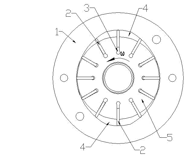
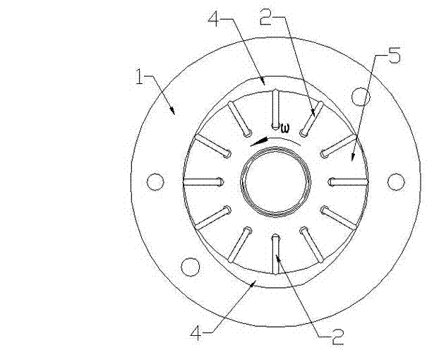
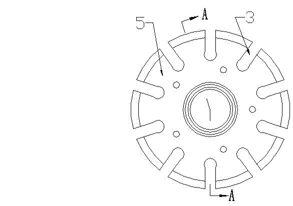
[0028]The structure of the vane pump with controllable vane stretching of the present invention includes a stator 1 and a rotor 5 , the rotor 5 is coaxially arranged in the stator 1 with gaps, and the rotor 5 can rotate in the stator 1 . The rotor 5 is provided with several vane slots 3 along its radial direction, and the openings of the vane slots 3 are located on the outer peripheral surface of the rotor 5 . Each vane slot 3 is provided with a vane 2 , and the dimension of the vane 2 along the axial direction of the rotor 5 is equal to or slightly smaller than the dimension of the vane slot 3 along the axial direction of the rotor 5 . When the rotor 5 rotates, the outer ends of the blades 2 can protrude to the outside of the rotor 5 under the action of centrifugal force. A cavity 4 is formed between the rotor 5 and the stator 1, and the inner wall of the stator 1 is similar to an ellipse. There are fluid suction area, fluid compression area and blade retraction area in the ...


PUM


Abstract

The invention discloses a blade pump with telescopic and controllable blades. The blade pump solves the problems that in the work process of the existing blade pump, the consumed energy is high, greater influence can be easily generated on work media, and the service life of the work media cannot be ensured. The blade pump with the telescopic and controllable blades is structurally characterized by comprising a stator and a rotor, wherein the rotor is rotatablely arranged in the stator, a plurality of blade grooves are arranged in the rotor in the radial direction, the blades are glidingly arranged in the blade grooves, and the blades can partially extend out of the radial outer side of the rotor or retracts into the rotor. A cavity is formed between the rotor and the stator, the cavity is provided with a fluid sucking region, a fluid compressing region and a blade retracting region, and two ends of a rotor and stator combined body are provided with end covers respectively. The blade pump is characterized in that a position limiting device used for limiting the sliding of the blades in the radial direction of the rotor is arranged on the rotor, and the position limiting device realizes the stable retraction of all blades into the rotor in a mode of being selectively clamped with the blades.

Description

technical field [0001] The present invention relates to a vane pump, in particular to a vane pump comprising a stator and a rotor. The rotor is provided with a plurality of vanes along the radial direction, and the vanes can be partially stretched out or retracted into the rotor. Background technique [0002] There are three main structural forms of pumps used to pump fluid, namely plunger pumps, gear pumps and vane pumps. Vane pumps are widely used in many mechanical fields because of their excellent working performance. [0003] The structure of the existing vane pump mainly includes a stator and a rotor, the rotor is rotatably arranged in the stator, and a cavity is formed between the stator and the rotor. The inner wall surface of the stator is approximately elliptical, so that a fluid suction area, a fluid compression area and a vane retraction area are formed in the cavity. A plurality of vane slots are arranged in the rotor along its radial direction, and a vane is s...

Claims


Application Information

Patent Timeline
IPC IPC(8): F04C2/344
Inventor 王新彪胡阳
Owner 胡阳
Why Eureka
Try Eureka