Magnetofluid disc brake

A magnetic fluid and disc brake technology, which is applied in the field of brake devices, can solve the problems of unfavorable environmental protection, easy loosening of hydraulic joints, and easy oil leakage of hydraulic systems, so as to save hydraulic oil resources and benefit the environment.

Inactive Publication Date: 2012-12-12
林智勇
View PDF0 Cites 16 Cited by
  • Summary
  • Abstract
  • Description
  • Claims
  • Application Information

AI Technical Summary

Problems solved by technology

[0002] Existing braking devices for motor vehicles and many equipment use the hydraulic system to drive the frictional resistance between the brake pads and the brake discs to brake. Because the oil pipes and seals of the hydraulic system are prone to aging, and the oil pressure joints are easy to loosen, etc., resulting in The hydraulic system is prone to failures such as oil leakage, which is not conducive to the safety of the brakes. At the same time, the widespread use of hydraulic oil is not conducive to environmental protection.

Method used


Image

  • Magnetofluid disc brake

Examples


Embodiment Construction

[0009] Below in conjunction with accompanying drawing, the present invention is further described:

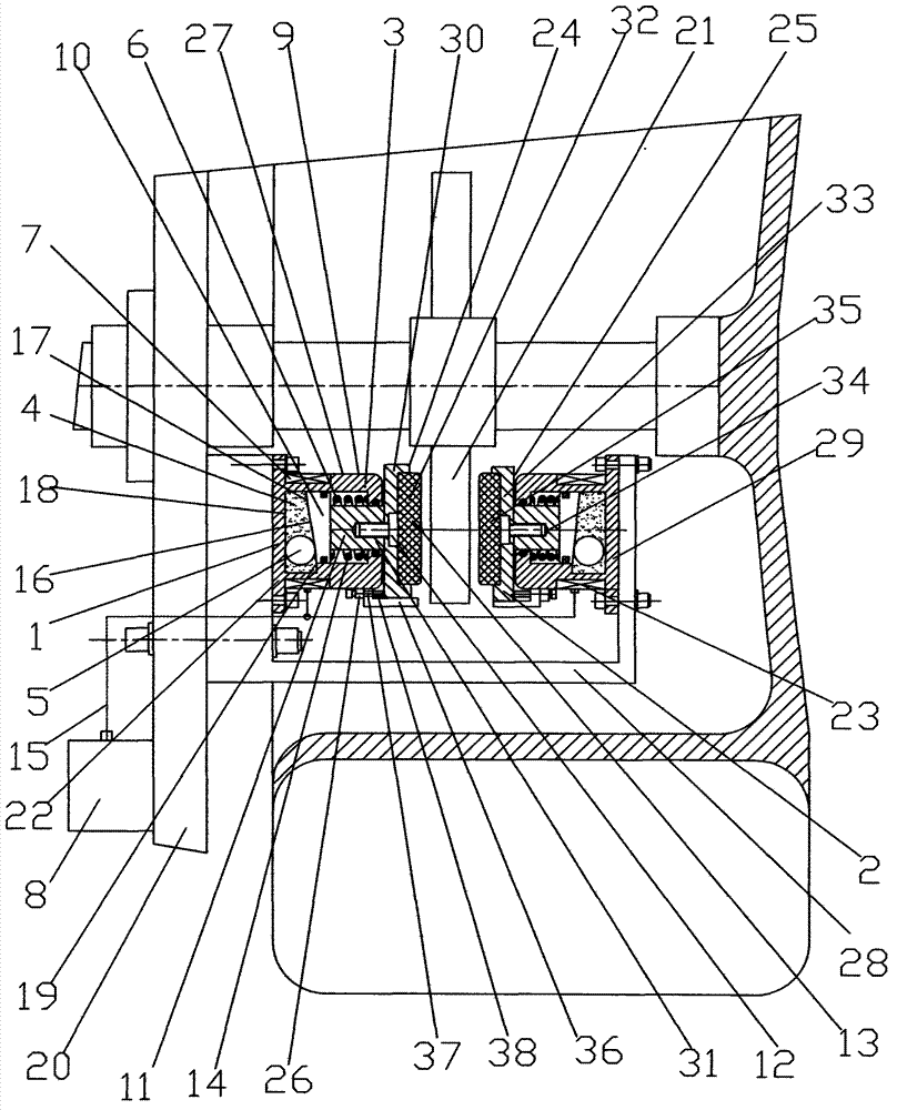
[0010] figure 1 A schematic structural diagram of a magnetic fluid disc brake is shown. A magnetic fluid disc brake includes a magnetic fluid brake drive device 1 and a brake device 2. The magnetic fluid brake drive device 1 includes a brake cylinder 3, a magnetic fluid 4, and a floating member 5. , an elastic element 6, an electromagnetic coil 7 and a controller 8; the brake cylinder 3 includes a cylinder body 9, a piston 10 and a piston rod 11, and the piston 10 is connected to the piston rod 11; the brake device 2 includes a brake seat 12 and a brake pad 13, The brake seat 12 is connected to the brake pad 13, the piston rod 10 is connected to the brake seat 12, the magnetic fluid 4 and the floating member 5 are arranged in the cylinder body 9, and the elastic element 6 is arranged between the piston 10 and the cylinder top 14 of the cylinder body 9, Electromagnetic coil 7 i...


PUM


Abstract

A magnetofluid disc brake comprises a magnetofluid brake drive mechanism and brake units, and the magnetofluid brake drive mechanism comprises brake cylinders, magnetofluids, floating parts, elastic elements, electromagnetic coils and a controller. A brake pedal and a brake switch are utilized to transmit a brake signal to the controller, the controller and the electromagnetic coils are utilized to control the magnetic fields of the magnetofluids in the brake cylinders, the change of the magnetic fields of the magnetofluids is utilized to control the floatage of the floating parts in the magnetofluids, the floatage of the floating parts is utilized to drive pistons and piston rods to move, the piston rods are utilized to drive brake bases and brake pads to be in frictional contact with a brake disc for braking, and thereby the purpose of utilizing the controller to control braking is implemented.

Description

technical field [0001] The invention relates to a braking device, in particular to a magnetic fluid disc brake. Background technique [0002] Existing braking devices for motor vehicles and many equipment use the hydraulic system to drive the frictional resistance between the brake pads and the brake discs to brake. Because the oil pipes and seals of the hydraulic system are prone to aging, and the oil pressure joints are easy to loosen, etc., resulting in The hydraulic system is prone to failures such as oil leakage, which is not conducive to the safety of the brakes. At the same time, the widespread use of hydraulic oil is not conducive to environmental protection. Contents of the invention [0003] The purpose of the present invention is to overcome the deficiencies of the prior art, to provide a magnetic fluid disc brake, which uses the specific gravity of the magnetic fluid in the controller, and uses the buoyancy of the floating part in the magnetic fluid to drive th...

Claims


Application Information

Patent Timeline
Patent Type & Authority Applications(China)
IPC IPC(8): F16D57/00
Inventor 林智勇
Owner 林智勇
Why Eureka
Try Eureka