Non-contact angular displacement sensor

An angular displacement sensor, non-contact technology, applied in the sensor field, can solve the problems of complex installation, large volume, complex structure of the non-contact displacement sensor, etc., to save installation space, improve processing and assembly efficiency, and avoid magnetic sensors. The effect of chip damage

Active Publication Date: 2016-01-20
北京和光飞翼机电科技有限公司
View PDF3 Cites 0 Cited by
  • Summary
  • Abstract
  • Description
  • Claims
  • Application Information

AI Technical Summary

Problems solved by technology

[0004] In order to solve the technical problems of complex structure, large volume and complicated installation of the non-contact displacement sensor in the prior art, the object of the present invention is to provide a non-contact miniature angular displacement sensor; the angular displacement sensor structure of the present invention Compact and easy to assemble, so as to realize miniaturization and miniaturization, and also eliminate the hidden danger of circuit damage that may be caused by unexpected situations during use

Method used


Image

  • Non-contact angular displacement sensor
  • Non-contact angular displacement sensor
  • Non-contact angular displacement sensor

Examples


Embodiment 1

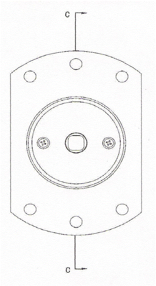
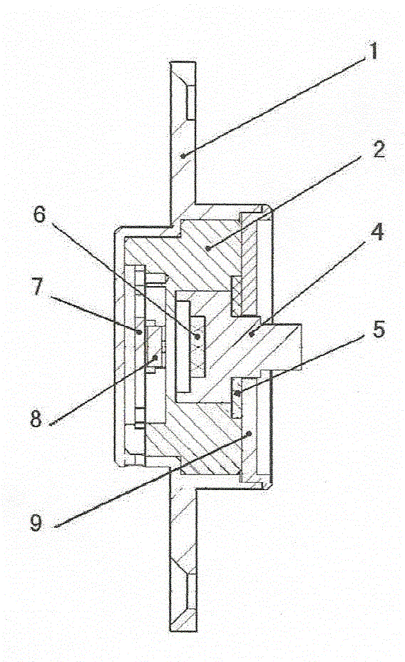
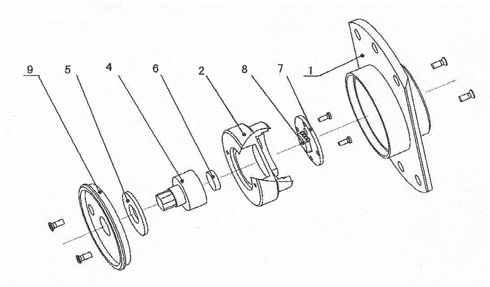
[0026] figure 1 with figure 2 It is the front view and c-c sectional view of the non-contact angular displacement sensor of this embodiment. The angular displacement sensor of this embodiment includes: outer shielding shell (1), inner shell (2), rotating shaft (4), and sealing elastic gasket (5) , magnet (6), wiring substrate (7), magnetic sensitive sensor (8) and front-end shielding cover (9). The outer shielding shell (1) with the flange surface and the front shielding cover (9) are matched and connected to form a complete magnetic shielding system. There is an outlet hole at the end of the outer shielding shell close to the wiring board to facilitate the extraction of sensor power and signal wires. The rotating shaft (4) made of stainless steel has a larger diameter end with a magnet concentrically bonded to the end face; the smaller diameter end shaft is processed into a connection structure with a certain length and a square section after extending out of the front shi...

Embodiment 2

[0031] Figure 4 with Figure 5It is the front view and c-c sectional view of the non-contact angular displacement sensor of this embodiment. The angular displacement sensor of this embodiment includes: outer shielding shell (1), inner shell (2), retaining ring (3), rotating shaft (4), Magnet (6), wiring substrate (7), magnetic sensitive sensor (8) and front-end shielding cover (9). The outer shielding case (1) with the flange surface includes all internal structures such as the inner case (2) as a whole, and is connected with the front shielding cover (9) to form a complete magnetic shielding system. There is an outlet hole at the end of the outer shielding shell close to the wiring board to facilitate the extraction of sensor power and signal wires. The rotating shaft (4) made of stainless steel has a larger diameter end with a magnet concentrically bonded to the end face; the smaller diameter end shaft is processed into a connection structure with a certain length and a s...


PUM


Abstract

The invention relates to a non-contact angular displacement sensor, comprising: an outer shielding case and a front-end shielding cover are matched and connected to form a complete magnetic shielding structure; the inner case has a rotationally symmetrical cavity structure; one end of the cavity structure is fixedly installed with a wiring substrate and The magnetic sensitive sensor forms the working area of ​​the electronic component; the other end of the cavity structure is equipped with a rotating shaft and a magnet to form a mechanical rotating working area, and the working area of ​​the electronic component and the mechanical rotating working area are not communicated with each other. The angular displacement sensor of the present invention has a compact structure and is easy to assemble, so that miniaturization and miniaturization can be realized, and the hidden danger of circuit damage that may be caused by unexpected situations during use can be eliminated.

Description

technical field [0001] The present invention relates to a sensor, and more particularly, the present invention relates to a non-contact miniature angular displacement sensor for detecting the rotational angular displacement of a rotating shaft. Background technique [0002] There are two types of output signal sensors currently used in industrial machinery and equipment. One is the mechanical type, that is, the contact type, which is in sliding contact with the resistance substrate through the brush. With the relative displacement, the resistance value changes, and the output voltage signal changes accordingly. Due to the vibration of the equipment, the contact piece may be disengaged instantaneously, resulting in poor contact; and during the application process, due to the wear debris of the brush and the resistor substrate will adhere between the brush and the resistor substrate, poor contact or output resistance will occur. The change of the value finally leads to the fa...

Claims


Application Information

Patent Timeline
Patent Type & Authority Patents(China)
IPC IPC(8): G01B7/30
Inventor 赵军
Owner 北京和光飞翼机电科技有限公司
Why Eureka
Try Eureka