Method for detecting shape and center of optical fiber and optical fiber coupling lens

A fiber coupling and lens technology, applied in optics, measuring devices, optical components, etc., can solve problems such as coupling loss of optical power connection, and achieve the effect of avoiding angle errors, easy to observe and judge images, and easy to observe and judge.

Active Publication Date: 2012-12-12
南京东利来光电实业有限责任公司
View PDF6 Cites 5 Cited by
  • Summary
  • Abstract
  • Description
  • Claims
  • Application Information

AI Technical Summary

Problems solved by technology

Since the core diameter of a multimode fiber is usually only 50-100 μm, if there is a mechanical alignment error between such thin fibers, the connection coupling loss of optical power will inevitably occur

Method used


Image

  • Method for detecting shape and center of optical fiber and optical fiber coupling lens
  • Method for detecting shape and center of optical fiber and optical fiber coupling lens
  • Method for detecting shape and center of optical fiber and optical fiber coupling lens

Examples


Embodiment 1

[0029] The method for detecting the shape and center of an optical fiber comprises the following steps:

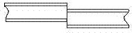
[0030] First, a fiber coupling lens is used to capture the light energy of the fiber, and the captured light energy passes through the fiber coupling lens to form spherical aberration. The fiber coupling lens includes a housing 1 and at least four groups of mirrors 2 arranged in the housing 1, two of which Each mirror group 2 is respectively arranged on the front part and the rear part of the overcoat 1, and is a front mirror group 2-1 and a rear mirror group 2-2; The positioning component 3 of the positioning mirror group 2, wherein, by installing an independent flat glass 4 for compensating the lens aberration on the fiber coupling lens, the light energy passes through the steel wire coupling lens to form spherical aberration, and the independent flat glass The glass 4 is arranged on the front portion of the jacket 1 and is positioned outside the front mirror group 2-1;...

Embodiment 2

[0033] The method for detecting the shape and center of an optical fiber comprises the following steps:

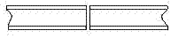
[0034]First, a fiber coupling lens is used to capture the light energy of the fiber, and the captured light energy passes through the fiber coupling lens to form spherical aberration. The fiber coupling lens includes a housing 1 and at least four groups of mirrors 2 arranged in the housing 1, each The lens center thickness of lens group 2 is 2mm, wherein two lens groups 2 are respectively arranged on the front part and the rear part of coat 1, are front lens group 2-1 and rear lens group 2-2, front lens group 2-1 and Between the rear mirror group 2-2 are the first middle mirror group 2-3 and the second middle mirror group 2-4; between the radial peripheral surface of each group of mirror group 2 and the outer cover 1, there is a mirror group 2 for positioning. positioning assembly 3; wherein, the spherical aberration is formed by changing the center thickness of the lens i...

Embodiment 3

[0037] The method for detecting the shape and center of an optical fiber comprises the following steps:

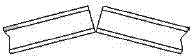
[0038] First, a fiber coupling lens is used to capture the light energy of the fiber, and the captured light energy passes through the fiber coupling lens to form spherical aberration. The fiber coupling lens includes a housing 1 and at least four groups of mirrors 2 arranged in the housing 1, two of which Two mirror groups 2 are respectively arranged on the front and the rear of the coat 1, and are the front mirror group 2-1 and the rear mirror group 2-2, between the front mirror group 2-1 and the rear mirror group 2-2 is the first middle Mirror group 2-3 and second middle mirror group 2-4; All are provided with the positioning component 3 that is used for positioning mirror group 2 between the radial peripheral surface of each group mirror group 2 and overcoat 1; Wherein, by changing mirror group 2 The thickness of the air layer between them forms spherical aberration; t...


PUM


Abstract

The invention discloses an optical fiber coupling lens which comprises an outer sleeve, at least four lens groups and independent plate glass. The independent plate glass is arranged at the front part of the outer sleeve and is positioned outside a front lens group. The invention also discloses a method for detecting the shape and the center of an optical fiber, which comprises the following steps of: firstly, capturing light energy of the optical fiber by the optical fiber coupling lens so as to form the spherical aberration after the captured light energy passes through the optical fiber coupling lens; and then analyzing the light energy with the spherical aberration by an image analyzer so as to judge the shape and the center of the optical fiber. The optical fiber coupling lens disclosed by the invention is provided with the independent plate glass, and thus, the lens can have a certain spherical aberration and the energy distribution is changed after the energy passes through the lens, so that an image which can be conveniently observed and judged is formed by the captured optical fiber energy. According to the method for detecting the shape and the center of the optical fiber, which is disclosed by the invention, by considering the light energy passing through the optical fiber coupling lens as the spherical aberration, the energy distribution is changed after the energy passes through the lens, so that the image which can be conveniently observed and judged is formed.

Description

technical field [0001] The invention relates to an optical fiber coupling device and a light detection method, in particular to a method for detecting the shape and center of an optical fiber and an optical fiber coupling lens for detecting the shape and center of an optical fiber. Background technique [0002] With the development and progress of science and technology, optical fibers are widely used as transmission media and sensing elements. Various types of optical fibers appear in different applications. Therefore, people pay more and more attention to the detection of optical fiber. In the application process of any fiber optic system, an important issue that must be considered is the low-loss connection method between fibers to ensure that the optical power in the fiber core can be effectively coupled to the core of another fiber through the connection to go. Mechanical alignment errors are a major problem when two fibers are spliced. Since the core diameter of th...

Claims


Application Information

Patent Timeline
Patent Type & Authority Applications(China)
IPC IPC(8): G01B11/24G01B11/00G02B7/02
Inventor 赵跃东
Owner 南京东利来光电实业有限责任公司
Why Eureka
Try Eureka