Optical current transformer and method for resisting external magnetic field interference

A current transformer and current sensor technology, applied in the direction of voltage/current isolation, measuring current/voltage, instruments, etc., can solve the problems of large volume and weight, limited shielding effect, complex insulation, etc., and achieve small size, low cost, Insulation and reliable effect

Active Publication Date: 2012-12-12
HARBIN INST OF TECH
View PDF2 Cites 10 Cited by
  • Summary
  • Abstract
  • Description
  • Claims
  • Application Information

AI Technical Summary

Problems solved by technology

[0009] The purpose of the present invention is to provide an optical current transformer and its method for realizing resistance to external magnetic field interference in order to solve the problems of limited shielding effect, complex structure, complex insulation, and large volume and weight in current optical current transformers

Method used


Image

  • Optical current transformer and method for resisting external magnetic field interference
  • Optical current transformer and method for resisting external magnetic field interference
  • Optical current transformer and method for resisting external magnetic field interference

Examples


specific Embodiment approach 1

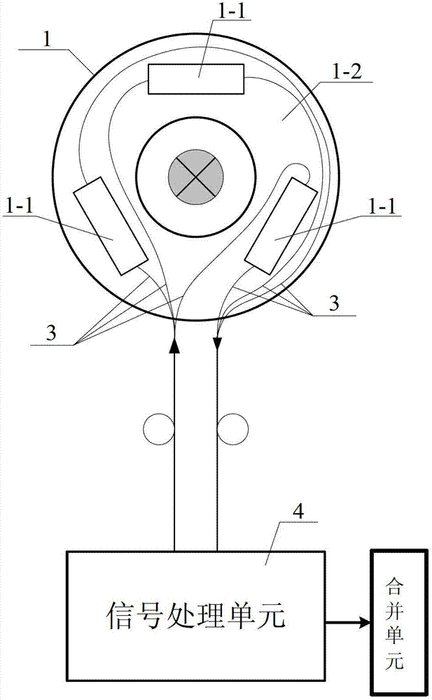
[0036] Specific implementation mode one: combine figure 1 and image 3 Describe this embodiment, the optical current transformer described in this embodiment includes an optical sensing unit 1, a signal processing unit 4 and a multimode optical fiber 3, and the optical sensing unit 1 includes m optical current sensors 1-1 and An insulating tray 1-2, m≥2; the m sets of optical current sensors 1-1 are the same straight-through optical current sensors 1-1, and the magneto-optical glass of the m sets of optical current sensors 1-1 passes along the The length of the light direction is l, and the m optical current sensors 1-1 are fixed on the insulating tray 1-2, and the m optical current sensors 1-1 independently output to the signal processing unit 4 through the multimode optical fiber 3; The m sets of optical current sensors 1-1 of the sensing unit 1 form a zero sum magnetic structure S m The optical signal input end of the optical sensing unit 1 communicates with the optical s...

specific Embodiment approach 2

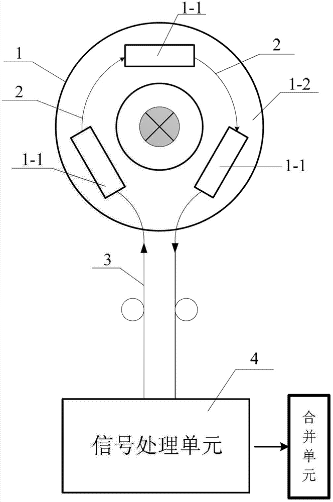
[0039] Specific implementation mode two: combination figure 2 and image 3 Describe this embodiment, the optical current transformer described in this embodiment includes an optical sensing unit 1, a signal processing unit 4, a polarization-maintaining optical fiber 2 and a multimode optical fiber 3, and the optical sensing unit 1 includes m optical current transformers A sensor 1-1 and an insulating tray 1-2, the m optical current sensors 1-1 are the same straight-through optical current sensors 1-1, the magneto-optical current sensors 1-1 of the m optical current sensors 1-1 The length of the glass along the light-passing direction is l, and m optical current sensors 1-1 are fixed on insulating trays 1-2 to form a series topology relationship, and polarization-maintaining optical fibers 2 are used between the m optical current sensors 1-1 connection; m sets of optical current sensors 1-1 of the optical sensing unit 1 form a zero sum magnetic structure S m The optical sign...

specific Embodiment approach 3

[0041] Specific Embodiment Three: This embodiment is a further limitation of the optical current transformer described in Embodiment 1 or Embodiment 2. The zero-sum magnetic structure S m are m directed straight line segments l k The m-order symmetric polygonal discrete loop formed, k=1, 2,..., m; the directed straight line segment l k is a short side, and the length of each short side is l, and the side between two adjacent short sides is a long side (or a directed straight line segment l k is the long side, this embodiment uses the short side as an example for illustration); the discrete loop satisfies the following two conditions:

[0042] 1. m long sides and m short sides constitute a symmetrical 2m polygon, and the symmetrical 2m polygon is a symmetrical 2m polygon inscribed in a circle;

[0043] 2. m directed line segments l k Take the opposite direction or the clockwise direction as the positive direction;

[0044] Take the zero and imperial magnetic structure S m ...


PUM


Abstract

The invention relates an optical current transformer and a method for resisting external magnetic field interference, and aims to solve the problems of limited shielding effects, complex structure, complexity in insulation, large size and great weight of the conventional optical current transformer. The optical current transformer comprises m through light path type optical current sensors. The length of magneto-optic glass of each optical current sensor along an incidence direction is 1. The optical current sensors are fixedly arranged on an insulating tray to form a zero-sum magnetic resistance structure S<m>. The optical current transformer comprises the m optical current sensors in a series-connected topological relationship, and the optical current sensors form the zero-sum magnetic resistance structure S<m>. The method for resisting the external magnetic field interference by using the optical current transformer comprises the following steps that a tested bus penetrates through the central position of the optical current transformer, interference current igr is positioned on a point P outside the plane loop of the S<m>, and the m optical current sensors are arranged according to the zero-sum magnetic resistance structure S<m>. The optical current transformer and the method for resisting the external magnetic field interference are applied to the field of current transformers of power systems.

Description

technical field [0001] The invention relates to an optical current transformer and a method for resisting external magnetic field interference. Background technique [0002] The current transformer is an indispensable power equipment in the power system. In recent years, various forms of electronic current transformers have been developed. Among them, the optical current transformer based on the principle of Faraday's magneto-optical effect has excellent performance and potential advantages. It has become the most ideal electronic current transformer and is the main direction of electronic current transformer development. According to the structure of the sensing optical path, the optical current transformer can be divided into a closed optical path type optical current transformer and a straight-through optical path type optical current transformer. The straight-through optical path type optical current transformer has a simpler structure, higher accuracy and reliability. ...

Claims


Application Information

Patent Timeline
Patent Type & Authority Applications(China)
IPC IPC(8): G01R15/24G01R19/00
Inventor 郭志忠于文斌张国庆申岩李深旺王贵忠路忠峰
Owner HARBIN INST OF TECH
Why Eureka
Try Eureka