Filtering type power transformer integrated system and implementation method thereof
A power transformer and integrated system technology, applied in the direction of transformer/inductor coil/winding/connection, harmonic reduction device, electrical component structure association, etc., can solve the problem of large filter cost investment, large harmonic injection into the grid, and harmonic High current and other problems, to improve the safe operation level, improve the power factor, reduce the effect of harmonic loss
- Summary
- Abstract
- Description
- Claims
- Application Information
AI Technical Summary
Problems solved by technology
Method used
Image
Examples
Embodiment 1
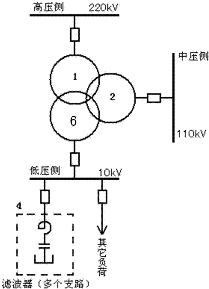
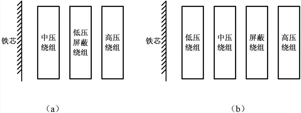
[0040] seefigure 1 and image 3 (a), the transformer of the filter-type power transformer integrated system adopts a three-winding structure, including high-voltage winding (voltage level is 220kV), medium-voltage winding (voltage level is 110kV) and low-voltage shielded winding (voltage level is 10kV). The low-voltage shield winding is set between the high-voltage winding and the medium-voltage winding (see image 3 (a)), the low-voltage winding is connected to the filter compensation device.
[0041] The filter device is designed according to full tuning, that is, for a certain harmonic (such as the 5th harmonic), the 5th harmonic reactance of the filter branch is equal to the 5th harmonic capacitive reactance, that is, ω 5 L=1 / ω 5 C, the total impedance of the branch is zero, realizing full tuning. The design principles of the filter branches of other harmonic orders are the same.
[0042] exist figure 1 Among them, the filter-type power transformer adopts a multi-wind...
Embodiment 2
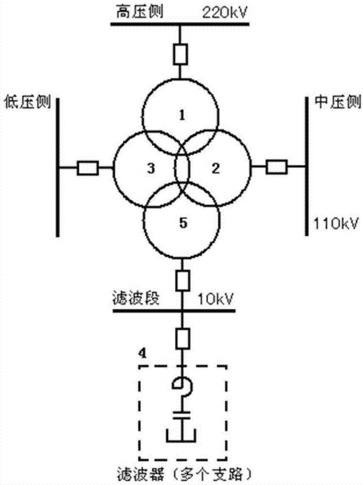
[0047] see figure 2 and image 3 (b), the transformer of the filter-type power transformer integrated system adopts a four-winding structure, including high-voltage windings (voltage level is 220kV), medium-voltage windings (voltage level is 110kV), low-voltage windings and shielded windings (voltage level is 10kV) . The shield winding is placed between the HV and MV windings (see image 3 (b)), the shielding winding is connected to the filter compensation device.
[0048] The filter compensation device (filter) is a series structure of reactor L and capacitor C, and the inductive reactance and capacitive reactance for a specific harmonic are equal, that is, ω n L=1 / ω n C, where ω is the fundamental angular frequency, and n is the harmonic order. The filter device is designed according to full tuning, that is, for a certain harmonic, taking the 5th harmonic as an example, the 5th harmonic reactance of the filter branch is equal to the 5th harmonic capacitive reactance, t...
PUM
 Abstract
Description
Claims
Application Information
 - R&D
- Intellectual Property
- Life Sciences
- Materials
- Tech Scout
- Unparalleled Data Quality
- Higher Quality Content
- 60% Fewer Hallucinations
Browse by: Latest US Patents, China's latest patents, Technical Efficacy Thesaurus, Application Domain, Technology Topic, Popular Technical Reports.
© 2025 PatSnap. All rights reserved.Legal|Privacy policy|Modern Slavery Act Transparency Statement|Sitemap|About US| Contact US: help@patsnap.com


