Connector

A technology of connectors and connecting caps, which is applied in the direction of connection, parts of connection devices, electrical components, etc., can solve problems such as hidden dangers of personal safety of operators, and achieve the effect of increasing separation time and ensuring safety

Inactive Publication Date: 2012-12-12
CHINA AVIATION OPTICAL-ELECTRICAL TECH CO LTD
View PDF4 Cites 17 Cited by
  • Summary
  • Abstract
  • Description
  • Claims
  • Application Information

AI Technical Summary

Problems solved by technology

But the existing problem of this kind of connector is: this kind of plug-in connector, often the plug and the socket begin to be directly separated once after the locking structure is unlocked, and the relay contact receives the signal from the control unit. It takes about 10~15ms to complete the electrical connection of the port. Usually, because the pulling force of the hand is greater than the separation force of the connector, under the action of acceleration and inertia, the separatio

Method used


Image

  • Connector
  • Connector
  • Connector

Examples


Embodiment Construction

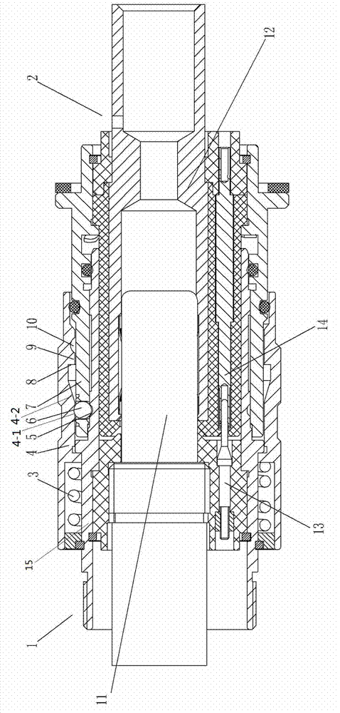
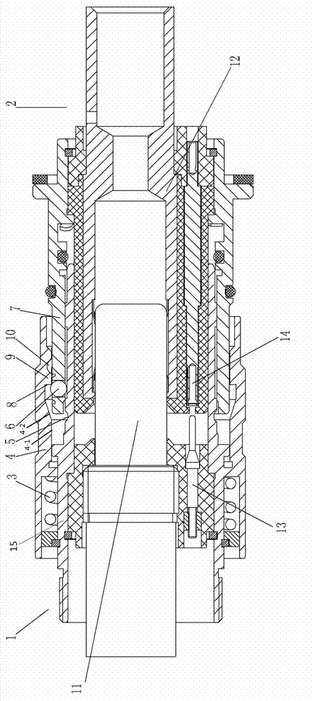
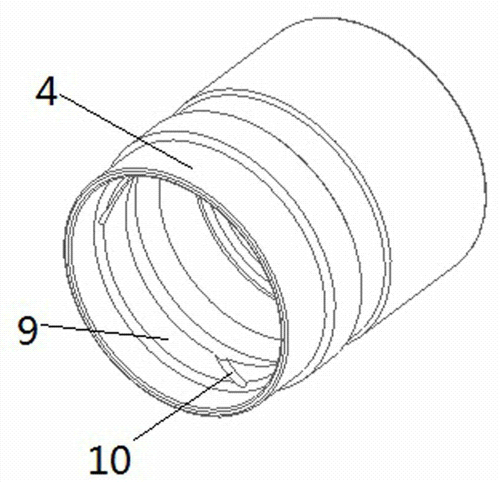
[0019] Examples of connectors are Figure 1~3 As shown: it includes a plug 1 and a socket 2 with the front end as a plug-in terminal. The plug 1 includes a plug housing 15 and a plug main contact 11 and a plug signal contact 13 assembled in the plug housing 15. The socket 2 includes a socket housing 7 And socket main contacts 12 and socket signal contacts 14 assembled in the socket housing 7 . The outer circumference of the plug housing 15 is equipped with a connecting cap 4 for the anti-off rotation of the axial direction, and an annular gap is arranged between the inner wall of the connecting cap 4 and the outer wall of the plug housing 15, and the front end of the socket housing 7 is inserted into the annular gap when connecting. There are three floating locking balls 6 evenly distributed on the socket connecting end in the circumferential direction, and the floating locking balls 6 have an outer convex part protruding from the outer peripheral surface of the socket housing...


PUM


Abstract

The invention relates to a connector. The connector comprises a plug case and a socket case, wherein a connection cap is arranged at the periphery of the plug case; the connection cap has a pressing part/recession part capable of matching with a locking ball location groove to lock/unlock a floating locking ball; the floating locking ball includes an outer protrusion part protruding the circumferential surface of the socket case; a stop stage is arranged on the inner wall of the connection cap in front the recession part, and has a stop surface for stopping the further separation of a plug and a socket in combination with the outer protrusion part when the plug is separated from the socket; a locking ball passage for allowing the locking ball to pass through for unlocking is arranged on the stop stage or between the stop stage and the inner wall of the connection cap; the locking ball passage has an inlet close to the right end and a outlet on the front end; the inlet allows the outer protrusion part to enter the locking ball passage from the stop surface when the connection cap rotates in position; and the outlet is used for extracting the outer protrusion part from the locking ball passage so as to separate the plug and the socket. The connector provided by the invention can prolong the separation time of the plug and the socket.

Description

technical field [0001] The invention relates to a connector for high voltage and high current. Background technique [0002] In order to prevent arcing when high-voltage and high-current connectors are disconnected and endanger personal safety, the high-voltage interlock technology of connectors came into being. The existing connector includes a plug and a socket that are locked together by a locking structure when they are mated. The plug includes a plug housing with a cylindrical structure and socket main contacts and socket signal contacts assembled therein. The socket housing and the plug main contacts and plug signal contacts assembled therein, wherein the insertion of the plug main contacts and the socket main contacts can realize the connection of corresponding electrical signals, and the plug signal contacts and socket signal contacts are used for Connect to the control unit interface of the main circuit relay of the circuit. The plugging stroke of the plug signal ...

Claims


Application Information

Patent Timeline
IPC IPC(8): H01R13/633H01R13/53
Inventor 王维桢张俊东
Owner CHINA AVIATION OPTICAL-ELECTRICAL TECH CO LTD
Why Eureka
Try Eureka