Multifunctional emergency lamp control system and control method thereof

A control system and emergency light technology, applied in the direction of electric light circuit layout, lighting devices, fire alarms, etc., can solve the problems of waste of energy, single function, and the monitoring of the Internet of Things by the control center, so as to reduce the number of casualties and prevent theft Events, time-saving effects

Inactive Publication Date: 2012-12-12
JINAN UNIVERSITY
View PDF7 Cites 11 Cited by
  • Summary
  • Abstract
  • Description
  • Claims
  • Application Information

AI Technical Summary

Problems solved by technology

[0004] (1) There is no anti-theft alarm function, and the function is single;
[0005] (2) When the power is off, it cannot automatically judge whether to turn on the emergency light according to the brightness of the ambient light. On the one hand, it wastes energy, and on the other hand, it shortens the life of the emergency light
[0006] (3) All the emergency lights currently installed in buildings or warehouses are relatively independent, and are not monitored by the control center through the Internet of Things, so the role of emergency lights cannot be fully utilized

Method used


Image

  • Multifunctional emergency lamp control system and control method thereof
  • Multifunctional emergency lamp control system and control method thereof
  • Multifunctional emergency lamp control system and control method thereof

Examples


Embodiment 1

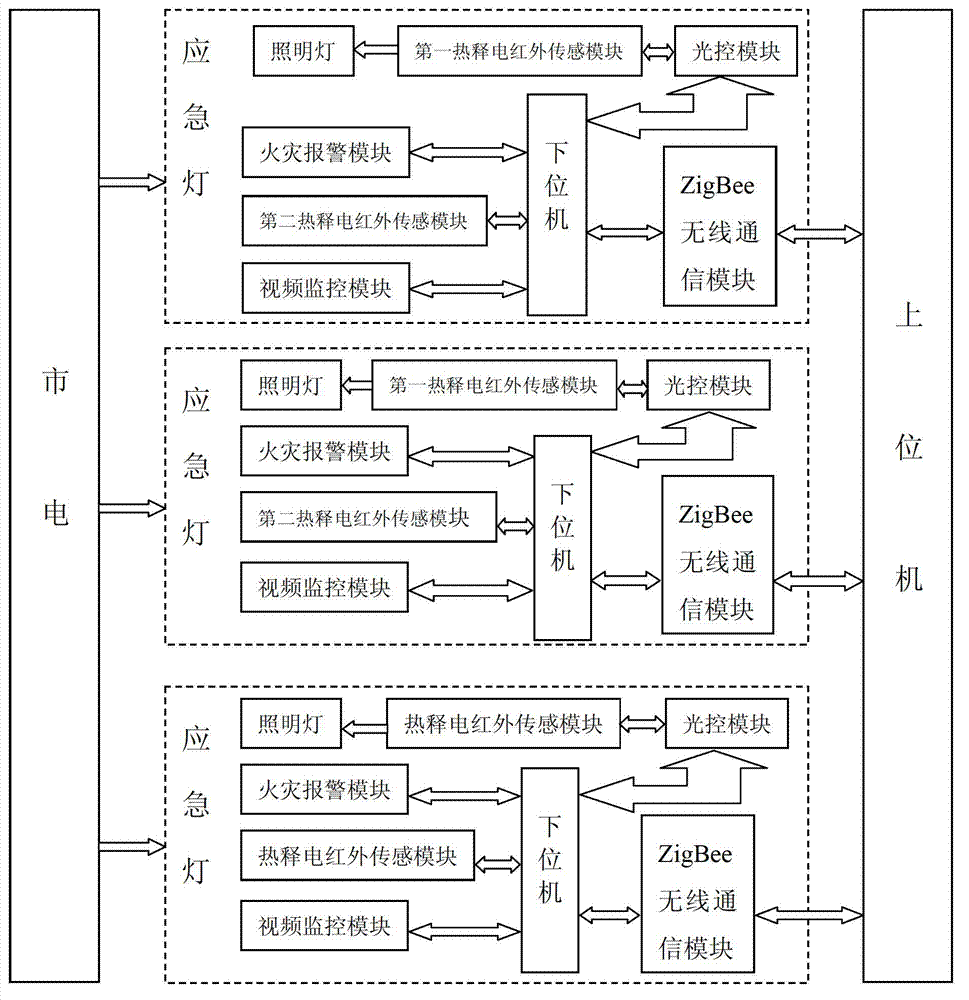
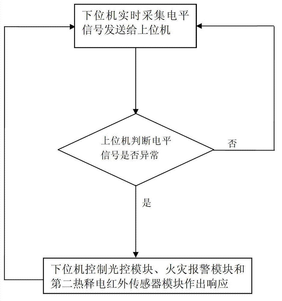
[0036] like figure 1As shown, a multifunctional emergency light control system includes a host computer and three emergency lights connected to the mains grid. The emergency lights include a ZigBee wireless communication module, a light control module electrically connected to the lower computer, and a fire alarm Module, the second pyroelectric infrared sensor module and video monitoring module, and the first pyroelectric infrared sensor module electrically connected with the light control module, the fire alarm module uses smoke sensors as fire detectors, the video monitoring module and The lower computer is electrically connected, the upper computer sends a wireless monitoring signal to the lower computer through the ZigBee wireless communication module, and the lower computer controls the light control module, the fire alarm module and the second pyroelectric infrared sensor module according to the wireless monitoring signal received , the lower computer collects the level ...

Embodiment 2

[0047] like Figure 4 As shown, this embodiment is the same as Embodiment 1 except for the following parts: the system includes an emergency light, and the system also includes a remote controller. The level signals of the fire alarm module and the second pyroelectric infrared sensor module are sent to the host computer and processed, and then the serial port sends instructions to the GSM wireless communication module, and the GSM communication module sends information to the user's mobile phone according to the received instructions. Let the user receive the abnormal situation in the area where the emergency light is located in time and take corresponding measures to reduce the loss of life and property. The function of the remote control is to turn on and off the GSM module. When the user himself is in the current area, it is not needed. SMS notification, press the remote control button to turn off the system at this time, and turn it on again when needed. The remote control...


PUM


Abstract

A multifunctional emergency lamp control system comprises an upper computer and a plurality of emergency lamps. Each emergency lamp comprises a wireless communication module, a light operated module, a fire alarm module, a second pyroelectric infrared sensor module and a first pyroelectric infrared sensor module. The control method of the multifunctional emergency lamp control system includes steps of firstly, acquiring level signals in real time and sending the level signals to the upper computer by a lower computer, continuously acquiring the level signals and sending the level signals to the upper computer by the lower computer if finding no abnormal level signals, and otherwise, executing the next step; secondly, sending numbers of the emergency lamps which send out the abnormal level signals and types of the abnormal level signals to the upper computer by the lower computer, and simultaneously, enabling the light operated module, the fire alarm module and the second pyroelectric infrared sensor module to make response under control of the lower computer; and thirdly, displaying relevant information through the upper computer. The emergency lamp control system has multiple functions of power-off illumination, burglary prevention and fire alarm, and has the advantages of high practicability and the like.

Description

technical field [0001] The invention relates to a network control technology for emergency lights, in particular to a multifunctional emergency light control system and a control method thereof. Background technique [0002] Power outages in the process of grid power supply occur from time to time, and power outage accidents caused by inadvertent use of electricity also exist from time to time. Therefore, it is necessary to install fire emergency equipment in public places or special places. The current emergency lighting equipment only needs to be activated when the power is off. The lights will be turned on, regardless of day or night, whether the light is sufficient, or whether there are people around. If the brightness is bright enough during the day or there is no one around the emergency lights, it will waste a lot of energy. This is in line with the energy saving and emission reduction advocated by the society In addition, the current emergency lights do not centrally...

Claims


Application Information

Patent Timeline
Patent Type & Authority Applications(China)
IPC IPC(8): H05B37/02G08B17/00G08B13/191
Inventor 潘小萍陈舜儿黄伟英邓声游吴梓欢谭炜丰陈建辉李秀丽
Owner JINAN UNIVERSITY
Why Eureka
Try Eureka