Machining method of high-accuracy cutter shaft of rotary shear

A processing method and disc shearing technology, applied in metal processing equipment, manufacturing tools, machine tools suitable for grinding workpiece planes, etc., can solve the unstable processing of product end face runout, the difficulty in evaluating the percentage of meshing surface, and the disadvantageous Produce high-precision products and other issues to ensure the coaxiality of products, avoid processing instability, and improve benchmark stability

Active Publication Date: 2012-12-19
CHANGZHOU BAOLING HEAVY IND MACHINERY
View PDF6 Cites 24 Cited by
  • Summary
  • Abstract
  • Description
  • Claims
  • Application Information

AI Technical Summary

Problems solved by technology

[0004] 1. Due to the characteristics of the material, it is difficult to ensure the stability of the central hole datum during the processing of the product
Due to the need to carry out different processes many times, the movement of the benchmark can easily lead to product scrapping
[0005] 2. During the grinding process, the runout of the end face of the product is unstable. Due to the influence of the grinding wheel of the grinder, it is easy to cause the beating of the grinding wheel when the side is ground. As a result, the accuracy requirement of 0.005um cannot be guaranteed (see figure 2 )
Difficult to form mass production, low efficiency, and prone to scrapping
[0007] 4. Conventional taper inspection methods require rich experience, and it is difficult to evaluate the percentage of the meshing surface
Not conducive to the production of high-precision products

Method used


Image

  • Machining method of high-accuracy cutter shaft of rotary shear
  • Machining method of high-accuracy cutter shaft of rotary shear
  • Machining method of high-accuracy cutter shaft of rotary shear

Examples


Embodiment Construction

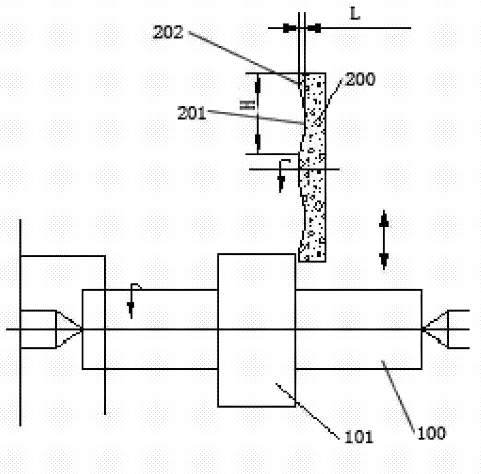
[0042] refer to image 3 , the axial end face grinding method of the shaft shoulder of the present invention, the shaft 100 is provided with a shaft shoulder 101, and a groove 201 is provided in the middle of the axial end face of the grinding wheel 200, the groove on the grinding wheel is an annular groove, and the grinding wheel 200 The vertical distance H between the peripheral surface and the inner annular surface of the groove 201 is greater than or equal to 1.5 times the height of the shoulder 101 . The distance L between the groove on the grinding wheel and the axial end surface of the grinding part is 1-2 mm. The part that is clamped between the groove 201 and the peripheral surface of the grinding wheel is the grinding part 202 of the grinding wheel, so that the grinding part of the grinding wheel in the rotating process is clamped on the machine tool and is in the end surface of the shaft shoulder in the rotating process. Grinding: During the grinding process, the g...


PUM


Abstract

The invention discloses a machining method of a high-accuracy cutter shaft of a rotary shear. The machining method is sequentially performed according to the following steps of: 1, forging a blank and normalizing; 2, performing rough turning; 3, performing hardening and tempering, i.e., performing quenching and high-temperature tempering treatment on the cutter shift; 4, performing semi-fine turning; 5, performing semi-fine milling; 6, performing fine turning; and 7, performing fine milling, i.e., milling a main outer circle and a taper of the cutter shaft, and meanwhile, arranging a groove in a middle part of an axial end face of a milling grinding wheel, wherein a part which is clamped between the groove and the circumferential surface of the grinding wheel is a milling part of the grinding wheel, so that the milling part of the grinding wheel in a rotation process is used for milling an end face of a cutter shaft shoulder which is kept in the rotation process after being clamped on a machine tool, and the grinding wheel does reciprocating motion in the radial direction of the cutter shaft in a milling process. According to the machining method, a contact area of the grinding wheel and the shaft shoulder can be reduced, jumping of a grinding wheel and aggravation of jumping of the shaft by resonance of an end face of the shaft shoulder and the grinding wheel in a milling process are prevented, and the milling accuracy of the axial end face is guaranteed to be within 0.005 mum.

Description

technical field [0001] The invention relates to the technical field of mechanical processing, in particular to a processing method for a high-precision knife shaft of disc shears. Background technique [0002] Disc shears are usually installed on the finishing line, and most cold rolling process lines use disc shears to trim or cut the longitudinal edges of the moving strip into narrow strips to remove edge defects of the strip. Accurate plate width and good edge formation are achieved by the rotary shearing motion of the upper and lower blades. The precision of disc shear equipment is high, the steel plate used for shearing is relatively thin, the gap between the scissors is about 0.02mm, and the runout of the end face of the cutter head is 0.01mm. If the gap is too large or the gap is uneven during the cutting process, the runout of the end face of the blade is too large There will be defects such as continuous cutting of the shear section, deformation of the steel plate,...

Claims


Application Information

Patent Timeline
Patent Type & Authority Applications(China)
IPC IPC(8): B24B7/16B23P15/00
Inventor 王淑娟陈国光徐春华
Owner CHANGZHOU BAOLING HEAVY IND MACHINERY
Why Eureka
Try Eureka