

Vertical double-electric-torque wrench
A torque wrench, vertical technology, applied in the field of vertical double electric torque wrench, can solve the problem of easy fatigue of operators, and achieve the effect of reducing labor intensity, solving easy fatigue and light weight
- Summary
- Abstract
- Description
- Claims
- Application Information
AI Technical Summary
Problems solved by technology
Method used
Image

Examples
Embodiment 1
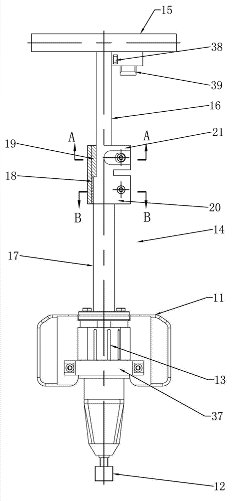
[0024] Such as figure 1 As shown, the vertical dual electric torque wrench of the present invention includes a vertical dual electric torque wrench, including a housing 11, a power output assembly, and a sleeve 12. The power output assembly is installed in the housing 11, and the power output assembly includes two batteries The motor 13 is connected to the battery, and the output shaft at the lower end of the motor 13 is drivingly connected to the sleeve 12.
[0025] A vertical rod 14 is fixedly installed at the upper end of the housing 11, the axis of the vertical rod 14 coincides with the axis of the output shaft of the motor 13, a vertical operating handle 15 is installed on the upper end of the vertical rod 14, and the middle of the vertical operating handle 15 arranged horizontally It is fixedly connected with the upper end of the vertical rod 14. The vertical rod 14 is a telescopic rod. In this embodiment, the vertical rod 14 includes an upper connecting rod 16 and a lower...
Embodiment 2
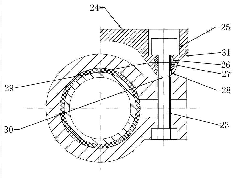
[0040] Such as Figure 4 As shown, the difference between this embodiment and Embodiment 1 is that the vertical rod 14 includes an upper connecting rod 16, a lower connecting rod 17 and a fixed rod 34, and two horizontally arranged two are provided on the outer circumference of the upper connecting rod 16. There are two first mounting holes 32, the lower connecting rod 17 is a hollow tube, the upper connecting rod 16 is inserted into the lower connecting rod 17, and the outer circumferential surface of the lower connecting rod 17 is provided with a number of second mounting holes 33, the second mounting holes 33 The distance between the two is equal, the axis of each second mounting hole 33 is parallel to the axis of the first mounting hole 32, the fixing rod 34 is fixedly inserted into a second mounting hole 33, and the fixing rod 34 passes through the first mounting hole 33. A mounting hole 32, the right end of the fixing rod 34 is provided with a tip 40, the diameter of the t...
Embodiment 3
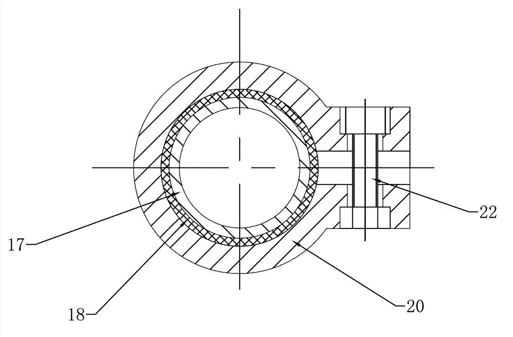
[0042] Such as Figure 5 As shown, the difference between this embodiment and Embodiment 1 is that the vertical rod 14 includes an upper connecting rod 16 and a lower connecting rod 17, and the cross-sectional shape of the upper connecting rod 16 is polygonal, such as a triangle, a quadrilateral or a pentagon. , Or as Image 6 As shown in the spline shape, the lower connecting rod 17 is a hollow tube, and the shape of the inner hole of the lower connecting rod 17 is consistent with that of the upper connecting rod 16. The upper connecting rod 16 is inserted in the lower connecting rod 17, outside the lower connecting rod 17. A third mounting hole 35 is opened on the circumferential surface, and a threaded jack 36 is installed in the third mounting hole 35. The upper connecting rod 16 is tightened and loosened by the threaded jack 36 to realize the upper connecting rod 16 and the lower connecting rod 16 The tightening and loosening between the rods 17 thereby adjust the length of...
PUM
 Abstract
Description
Claims
Application Information