Electrolyte plasma polishing machine for mass production

A plasma and polishing machine technology, which is applied in the field of ion polishing machines, can solve the problems of unsuitable enterprises for mass production and low production efficiency of polishing equipment, and achieve the effect of increasing the polishing area

Active Publication Date: 2014-10-15
HARBIN INST OF TECH
View PDF4 Cites 2 Cited by
  • Summary
  • Abstract
  • Description
  • Claims
  • Application Information

AI Technical Summary

Problems solved by technology

[0003] In order to solve the problem that the existing polishing equipment has relatively low production efficiency and is not suitable for mass production in enterprises, the present invention further provides an electrolyte plasma polishing machine for mass production

Method used


Image

  • Electrolyte plasma polishing machine for mass production
  • Electrolyte plasma polishing machine for mass production
  • Electrolyte plasma polishing machine for mass production

Examples


specific Embodiment approach 1

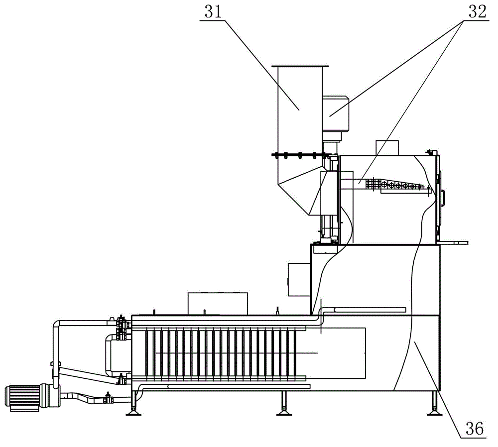
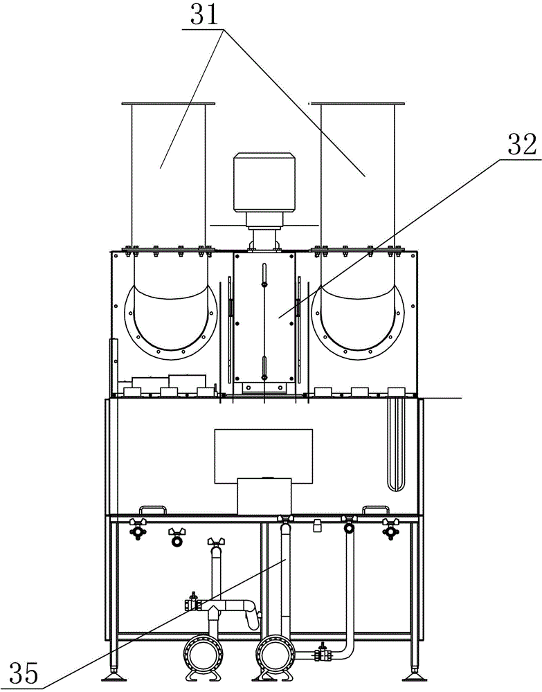
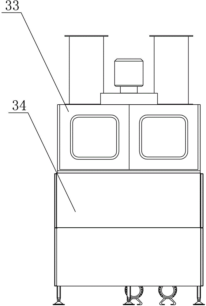
[0010] Specific implementation mode one: as Figure 1-10 As shown, the electrolyte plasma polishing machine for mass production in this embodiment includes a hanger and a lifting device 32, a working upper box 33, a working box 34, a liquid storage tank 36, a circulating stirring device 35 and two exhaust recovery devices 31. Case 34 is installed on the upper end face of liquid storage tank 36, and circulating stirring device 35 is installed on the sidewall of liquid storage tank 36 and both communicate with each other, and upper case 33 of work is positioned at the upper end face of working case 34, and two exhaust Recovering device 31 is relatively installed on the side wall of upper case 33 of work, and lifting device 32 is positioned between two exhaust air recovery devices 31 and is installed on the described side wall of upper case 33 of work; Each exhaust wind recovery device 31 It includes an exhaust air recovery pipeline 31-1, a catcher 31-2, two baffles 31-4 and a pl...

specific Embodiment approach 2

[0015] Specific implementation mode two: as figure 1 As shown, in this embodiment, a plurality of through holes 31-5 are evenly distributed along the circumferential direction. Other components and connections are the same as those in the first embodiment.

specific Embodiment approach 3

[0016] Specific implementation mode three: as figure 1 As shown, the diameter of the plastic ball 31-3 in this embodiment is 10 mm. Other compositions and connections are the same as those in Embodiment 1 or 2.

[0017] working principle:

[0018] Connect the workpiece to the anode with a wire, start the servo motor 1, the output shaft of the servo motor 1 drives the screw rod 21 to rotate, the screw rod 21 rotates to drive the screw nut sleeve 24 to move downward, and at the same time drives the conductive hanger 29 and the workpiece to be polished to slowly sneak into the In the polishing liquid, the polishing liquid is evaporated due to the instantaneous short circuit of the system to form a gas layer surrounding the workpiece, which completely separates the workpiece from the polishing liquid; the above gas layer enters the plasma state under the action of the voltage, and the workpiece to be polished is polished; During the polishing process, the polishing liquid is eva...


PUM

PropertyMeasurementUnit
diameteraaaaaaaaaa

Abstract

The invention provides an electrolyte plasma polisher for quantity production and relates to a plasma polisher, and the electrolyte plasma polisher is used for solving the problems that the existing polishing equipment is relatively low in production efficiency and is not suitable for large-batch production of enterprises. A circular stirring device is installed on the side wall of a liquid storage box, and the circular stirring device and the liquid storage box are mutually communicated; a top work box is located on the upper end surface of a work box; two air exhaust recovery devices are relatively installed on one side wall of the top work box; a lifting device is located between the two air exhaust devices and mounted on the side wall of the top box wall; each air exhaust device comprises an air exhaust recovery pipeline, a catcher, two baffles and a plurality of plastic balls; each catcher is arranged in the middle of each air exhaust recovery pipeline; the two baffles are horizontally arranged on the upper part of each air exhaust recovery pipeline; the plurality of plastic balls are arranged between the two baffles; and a plurality of through holes are formed in the two baffles along the axial direction. The electrolyte plasma polisher for quantity production is used for polishing machined parts on large scale.

Description

technical field [0001] The invention relates to a plasma polishing machine, in particular to an electrolyte plasma polishing machine for mass production. Background technique [0002] According to the electrolytic plasma polishing mechanism, when other conditions remain unchanged, the maximum polishing area of ​​the equipment is proportional to the power of the equipment, the greater the power, the larger the maximum area that can be polished or for small parts that can be polished at one time The higher the number of parts. The maximum power of the existing polishing equipment is 40kW, the production efficiency is relatively low, the maximum area that can be polished is small, and the polishing liquid needs to be replenished frequently during the processing, which is not suitable for mass production of enterprises. Contents of the invention [0003] In order to solve the problem that the existing polishing equipment has relatively low production efficiency and is not sui...

Claims


Application Information

Patent Timeline
Patent Type & Authority Patents(China)
IPC IPC(8): C23F4/00C25F3/16C25F7/00
Inventor 索来春王季关丽丽余海迪姜兆滨索景宇
Owner HARBIN INST OF TECH
Why Eureka
Try Eureka