Built-in rail-changing sliding window

A technology of sliding windows and window strips, which is applied in the field of sliding windows, can solve the problems of affecting the sealing effect, short service life, rainwater penetration and sliding, etc., and achieve the effect of improving vehicle grade, improving comfort and increasing safety

Active Publication Date: 2012-12-19
浙江瑾达汽车零部件股份有限公司
View PDF5 Cites 23 Cited by
  • Summary
  • Abstract
  • Description
  • Claims
  • Application Information

AI Technical Summary

Problems solved by technology

[0003] As far as the current sliding window is concerned, there are problems such as noise disturbance when pushing and pulling, rainwater seeping into the car due to long-term use, and inconvenient sliding. After a long time of pushing and pulling, the friction parts at the lower end of the sliding window will wear out, making The height of the movable window body has decreased, thus destroying the stability of the movable window on the slide rail set on the outer window frame, and most of the sliding windows are equipped with a sliding block or an opening handle integrated with the sliding block on the inner window wall. Install a fastener on the outer window frame to match the opening handle to realize the fixing of the movable window. Although the fixing method is simple, it will happen that the movable window cannot be pushed after a long time or if the strength is not enough during use. The opening of this structure The handle directly causes the sliding glass on the movable window of this type of sliding window to not be on the same plane as the fixed glass on the outer window frame. Part of the reason is that the slide rail is located on the inner side of the outer window frame and the fixed glass plane of the outer window frame is Staggered, when the movable window is closed, the sliding rail makes the movable window not be level with the outer wall of the outer window frame, and there is a large gap, so it is not suitable for high-end vehicles, and furthermore, it is not harmonious with the body design and the sealing effect is poor
[0004] Taking the noise noise when pushing and pulling as an example, most of the reasons come from the design of the slide rail. The current vehicle solution is generally to use a material with less noise during friction as the slide rail material, or change the sliding friction to rolling friction, but , the change of the material of the slide rail will increase the cost, and changing the sliding friction to rolling friction will make the movable window slide on the outer window frame unstable, because the sliding speed cannot be effectively controlled, and the sliding glass on the movable window is closed. The fixed glass on the outer window frame is not on the same plane, giving a very uneven appearance
[0005] Take the rainwater penetration into the car as the airtightness decreases after using for a long time. The current vehicle solution is to increase the airtightness between the movable window and the outer frame window. Generally, a sealant strip is used, and there is also a drainage device outside the outer frame window. , the drainage parts are collected through the sump set on the slide rail and then discharged from the drainage parts, but this kind of design makes the appearance of the sliding window rougher, and also affects the sealing effect
[0006] As far as the current sliding window is concerned, there is still a problem of short service life. If the window is not opened for a long time, the movable window will be locked on the slide rail due to the thermal expansion and contraction of the sealing strip, and it will be difficult to push and pull. Reduced airtightness

Method used


Image

  • Built-in rail-changing sliding window
  • Built-in rail-changing sliding window
  • Built-in rail-changing sliding window

Examples


Embodiment approach 1

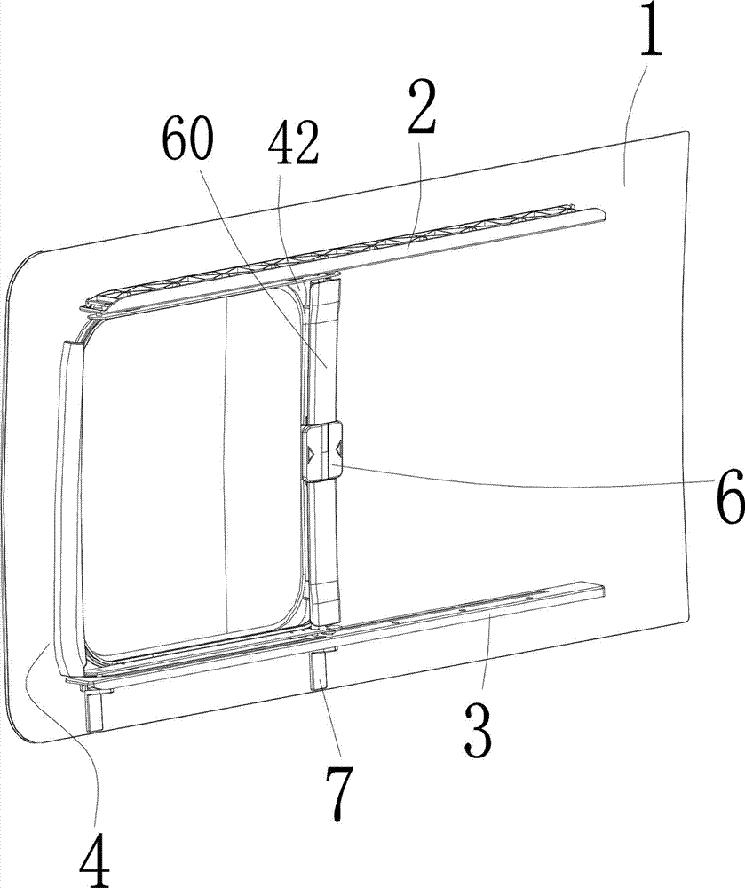
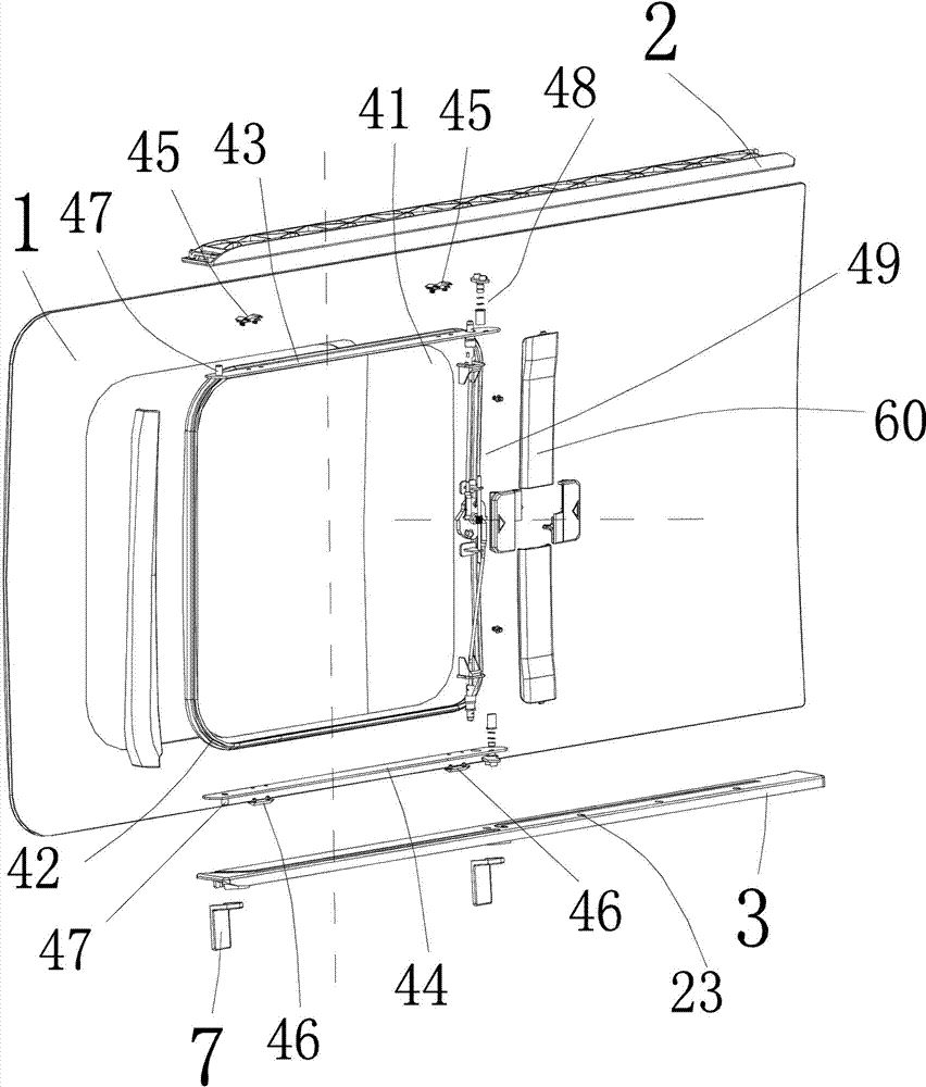
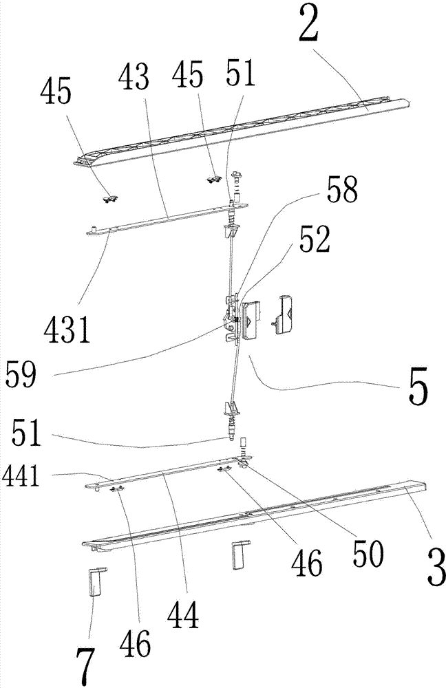
[0063] Embodiment 1, the built-in rail-changing sliding window includes upper and lower rails (2, 3) fixed on the inner side of the outer window frame (1), and movable between the upper and lower rails (2, 3) window (4), the movable window (4) includes upper and lower window strips (43, 44), the upper liner (45) installed on the upper window bar (43) and the lower liner (46) on the lower window bar (44) and the same end of the upper and lower window bars (43, 44) The sliding column (47) is composed of a rail-changing slider (48) inserted at the other same end of the upper and lower window bars (43, 44);

[0064] The upper and lower rails (2, 3) are evenly divided into two sections of chute, the end of the first section of chute (21) corresponding to the sliding post (47) is an arc, and the end of the first section of chute (21) corresponding to the sliding rail slider (48) is curved. The end of the second section of the chute (22) is hook-shaped; the end of the second section...

Embodiment approach 2

[0066] Embodiment 2, based on Embodiment 1, the upper pad (45) is composed of an M-shaped compensating elastic member (451) at the upper end, and a pad (452) connected with the compensating elastic member (451) at the lower end, There is a bullet-assisted metal strip (454) under the wings (453) that make up the two ends of the elastic member (451), and a quick positioning pin fixed on the upper window liner hole (431) extends below the pad (452). column (455), the column body of the quick positioning column (455) is in the shape of an inverted tower.

[0067] The upper surface of the compensating elastic part (451) is pushed against the rail surface of the upper slide rail (2). After the movable window (4) has been used for a long time, the elastic part (451) can be compensated under the action of the elastic metal strip (454). Both side wings (453) keep an elastic overhead state.

[0068] The quick positioning post (455) is in the shape of an inverted tower to ensure that th...

Embodiment approach 3

[0069] Embodiment 3, based on Embodiment 1, the surface of the lower gasket (46) has a tubular shape, and the other side of the gasket extends outwards with a positioning column (461) fixed to the gasket hole (441) of the lower window strip , the surface of the lower pad (46) is pressed against the surface of the lower rail (3).


PUM


Abstract

A built-in rail-changing sliding window comprises an upper sliding rail, a lower sliding rail and a moving window arranged between the upper and the lower sliding rails; the moving window comprises an upper window strip, a lower window strip, an upper liner, a lower liner, sliding pillars and rail-changing sliding bocks, wherein both the upper window strip and the lower window strop are arranged on a sliding glass fixing base, the upper liner is arranged on the upper window strip while the lower liner is arranged on the lower window strip, the sliding pillars are respectively arranged on the same ends of the upper window strip and one end of the lower window strip; the rail-changing sliding bocks are respectively arranged on the other same ends of the upper window strip and the lower window strip; each of the upper and the lower sliding rails is provided with two sections of sliding chutes, the end of each first section of sliding chute corresponding to each sliding pillar is of an arc shape, the end of each second section of sliding chute corresponding to each rail-changing sliding block is of a hook shape; and a lock hole matched with a bolt which is pushed out by a lock rotating mechanism in a lock box at the side of the sliding glass fixing base is respectively arranged on the surface of each of the upper and the lower sliding rails. The built-in rail-changing sliding window is long in service life and is more stable, more comfortable, good in overall appearance and excellent in waterproof property when in use; when the moving window is closed, sliding glass and outer window fixing glass can be realized on the same plane; with the adoption of an opening handle, the indoor comfortable degree is enhanced, and the vehicle grade is improved; and the window is beneficial to mass production and has higher practicability.

Description

technical field [0001] The invention relates to a sliding window, in particular to a built-in rail changing sliding window for automobiles. Background technique [0002] Automobiles are becoming more and more popular, and sliding windows on large and medium-sized passenger cars, commercial vehicles, and vans are a must-have part for the car body. Nowadays, the sliding window has been integrated with the car body design. The idea of ​​how to make the car body look beautiful and harmonious with the car body, and even bring more safety and convenience to passengers has already replaced the basic function of the original sliding window for ventilation and rain protection. [0003] As far as the current sliding window is concerned, there are problems such as noise disturbance when pushing and pulling, rainwater seeping into the car due to long-term use, and inconvenient sliding. After a long time of pushing and pulling, the friction parts at the lower end of the sliding window wi...

Claims


Application Information

Patent Timeline
Patent Type & Authority Applications(China)
IPC IPC(8): E06B3/46E06B7/14E05D13/00E05C17/60E05C19/00B60J1/00
Inventor 王雪华
Owner 浙江瑾达汽车零部件股份有限公司
Why Eureka
Try Eureka