Lubricant circulating device based on sliding bearing and manufacturing process of lubricant circulating device

A circulation device and sliding bearing technology, which is applied in the direction of engine lubrication, bearing components, bearing cooling, etc., can solve the problems of equipment system loss, burning tiles, and rise in input oil temperature, so as to improve the cooling effect and expand the application range.

Active Publication Date: 2012-12-19
HUNAN CHONGDE IND TECH
View PDF6 Cites 10 Cited by
  • Summary
  • Abstract
  • Description
  • Claims
  • Application Information

AI Technical Summary

Problems solved by technology

However, the existing circulating oil lubricated sliding bearings send the cooling lubricating oil directly into the oil tank, which will inevitably cause the cold oil to mix with the hot oil lubricated by the bearing and then enter the bearing again for lubrication, so that the temperature of the input oil

Method used


Image

  • Lubricant circulating device based on sliding bearing and manufacturing process of lubricant circulating device
  • Lubricant circulating device based on sliding bearing and manufacturing process of lubricant circulating device
  • Lubricant circulating device based on sliding bearing and manufacturing process of lubricant circulating device

Examples


Example Embodiment

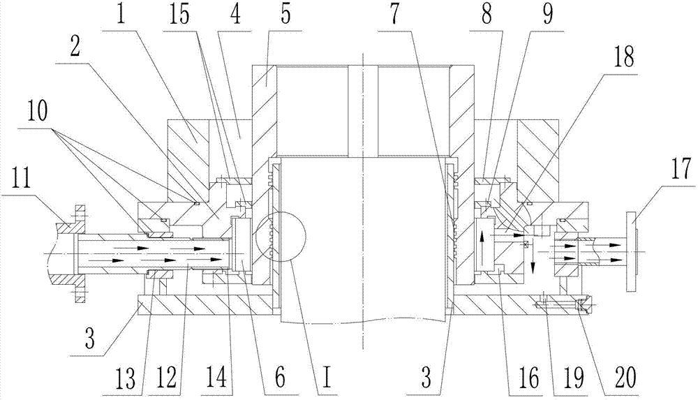
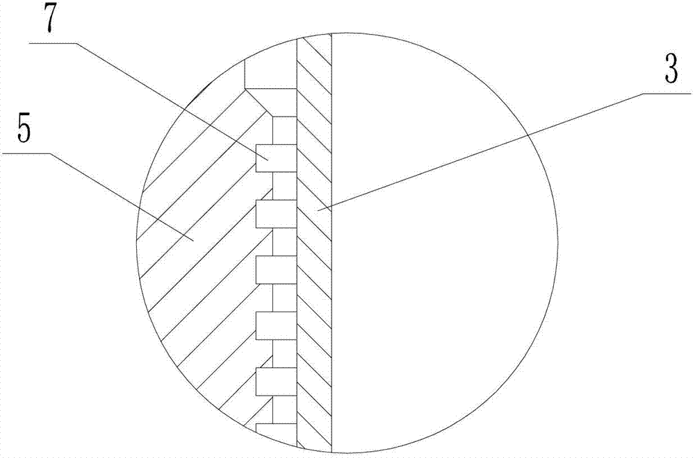
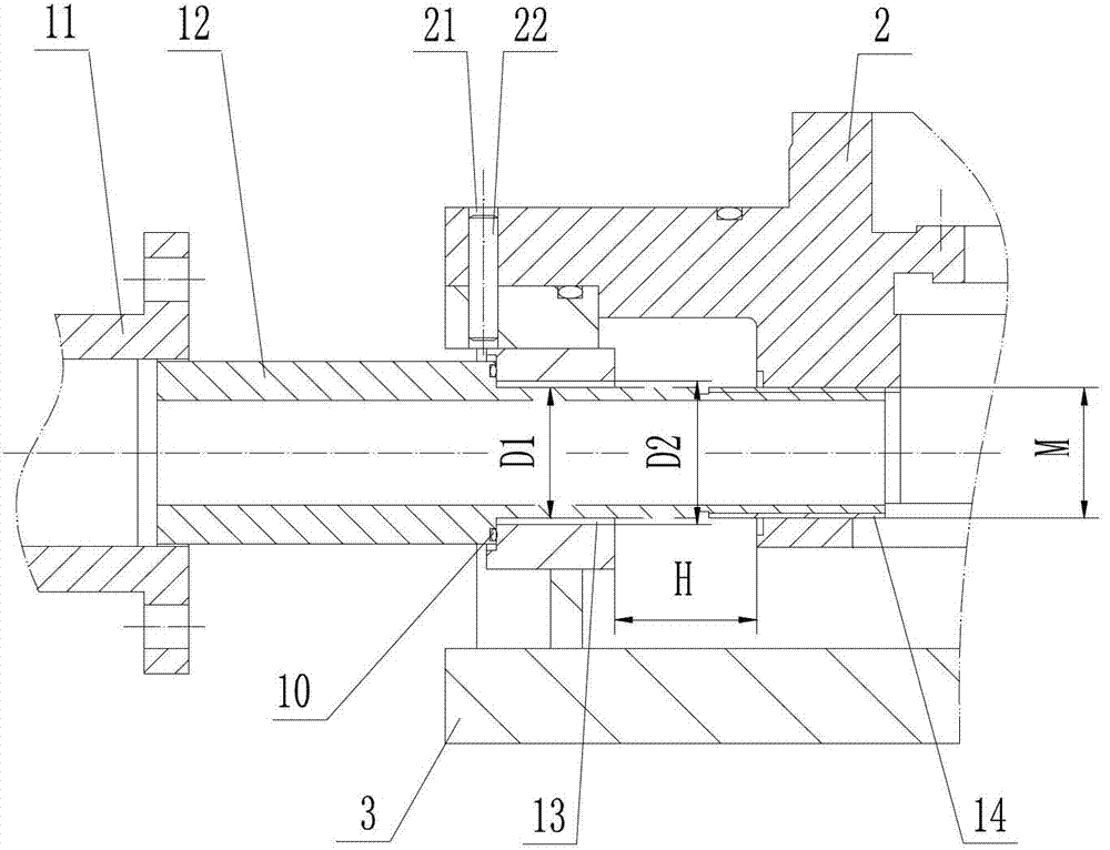
[0045] As shown in the figure, a lubricating oil circulation device based on a sliding bearing mainly includes a guide seat 2 fixed to the bearing bracket 1, an oil tank 3 connected to the guide seat 2, and a vertical shaft hole 4 is provided in the center of the guide seat 2 , The shaft hole 4 is provided with a shaft sleeve 5 and a bearing bush 6. In order to enhance the sealing effect, at least 6 radial labyrinth-shaped shaft sleeve sealing ring grooves 7 are provided in the shaft sleeve 5, and a large sealing pressure plate 8 is provided outside the shaft sleeve 5 , Small sealing pressure plate 9, large and small sealing pressure plates are collectively referred to as pressure plates, oil tank 3 and guide seat 2, guide seat 2 and bearing bracket 1, oil pipe 12, hot oil output pipe 17 and oil tank 3 are all equipped with O type The sealing ring 10, an oil pipe 12 connected to the interface of the cold oil input pipe 11 passes through the pipe mounting hole 13 of the oil tank ...


PUM


Abstract

The invention discloses a lubricant circulating device based on a sliding bearing, as well as a manufacturing process of the lubricant circulating device. The lubricant circulating device essentially consists of a bearing bracket, a guide base and an oil tank; an oil transportation duct which is connected to a port of a cold oil inputting pipe penetrates a duct mounting hole of the oil tank and is connected to a thread hole of the guide base, and is communicated with a cold oil storing cavity; a hot oil outputting pipe is connected to the oil tank and is communicated with an oil returning hole, thereby forming a system-cold oil-hot oil/cold oil-lubricant circulating-inputting/outputting loop; meanwhile, under the synchronous control of various corresponding equipment, the scheme of arranging the lubricant circulating inputting/outputting loop system is implemented. Through the lubricant circulating device, the sliding bearing which is matched with the motor, the water pump and other host equipment is not only compactly structured but is adaptive to the high-speed operation of the host equipment, and the sliding bearing cannot change the connecting and mounting size of the original machine and can ensure the circulation of the lubricant; the bearing bush can not generate heat; the equipment system is stable, reliable and safe in operation; the lubricant circulating device is suitable to be used as a supporting product of various power equipment, especially for as a supporting product of various heavy-load engineering machineries.

Description

Technical field [0001] The invention relates to a lubricating oil circulation device based on a sliding bearing and a manufacturing process thereof. Background technique [0002] At present, the main equipment such as motors, water pumps and other host equipment require supporting sliding bearings. Firstly, the sliding bearing structure needs to be compact, and secondly, the sliding bearing function needs to have the characteristics of high-speed operation, and the use is stable, reliable, safe, effective, and long in service life. The existing circulating oil-lubricated sliding bearings send cooling lubricating oil directly into the oil tank. This will inevitably cause the cold oil to mix with the hot oil that has been lubricated by the bearing and then enter the bearing for lubrication again, which makes the temperature of the input oil continue to rise and lubricate. The cooling effect is poor, and in severe cases, the bearing bush temperature is too high or the bushing is bur...

Claims


Application Information

Patent Timeline
IPC IPC(8): F16N11/00F16C37/00B23P15/00
Inventor 刘小军肖菊香周少华
Owner HUNAN CHONGDE IND TECH
Why Eureka
Try Eureka